Máquina de endurecimiento por inducción de engranajes de rodamiento giratorio para excavadoras, Grúas y Equipo Pesado
Ⅰ. See External Gear Induction Hardening in Operation
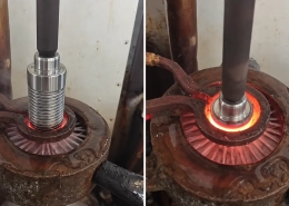
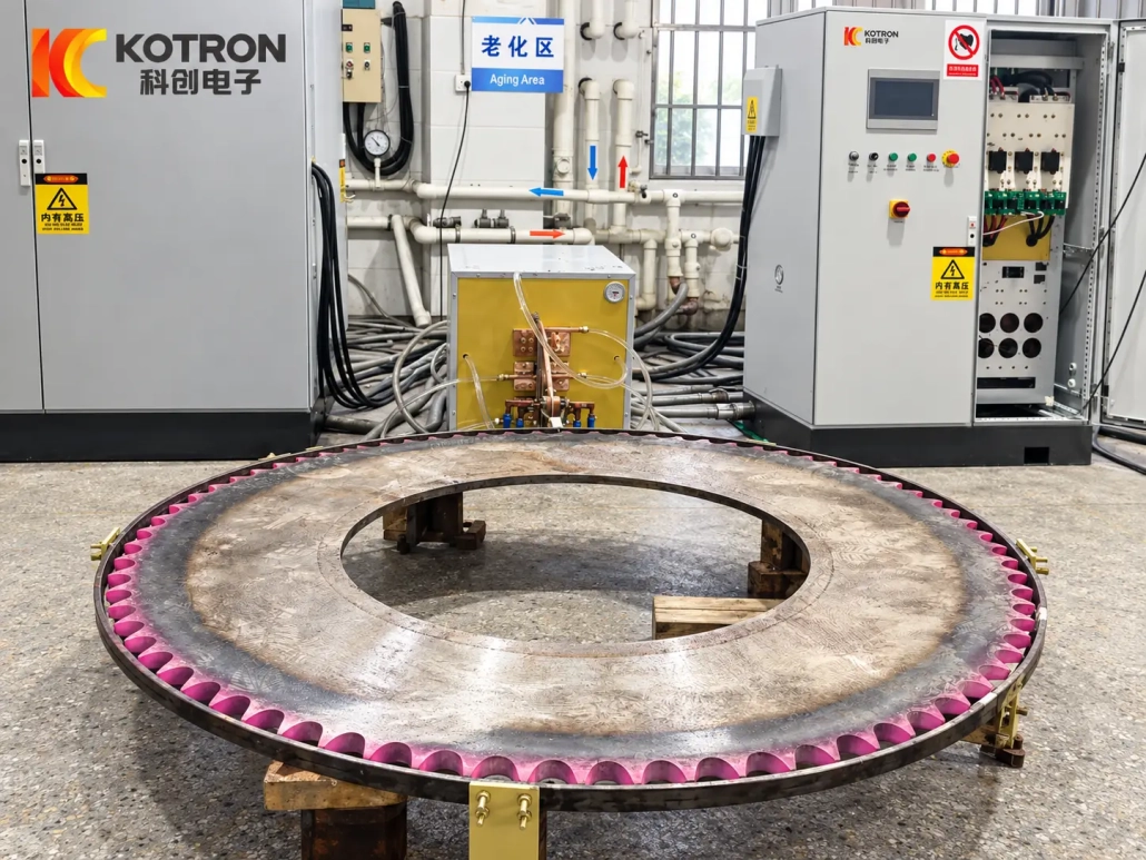
The video shows a real external-gear slewing bearing during the induction heating stage. The heated tooth area becomes visibly red before quenching.
This is one external-gear application. A different slewing ring may require another machine arrangement, inductor geometry or motion path depending on its diameter, gear position, module and required hardened zone.
The visible heating condition in the video is shown as a process reference only. Final process parameters are established from the actual workpiece and heat-treatment specification.
Ⅱ. What Can the Machine Harden?
A slewing bearing gear induction hardening machine can be configured around different geared slewing-ring structures and hardening requirements.
Las aplicaciones típicas incluyen:
•Internal slewing bearing gears
•External slewing bearing gears
•Tooth flank hardening
•Tooth flank and root hardening
•Selected gear-tooth zones
•Large-diameter slewing rings
•Custom gear hardening applications for heavy rotary components
A similar outside diameter does not necessarily mean two slewing bearings can use the same process.
Módulo de engranajes, geometría del diente, material, peso de la pieza de trabajo, required case depth and the position of the hardened zone all affect the machine and inductor design.
Por esta razón, the workpiece drawing is normally the starting point for equipment selection.
Ⅲ. Internal and External Gear Hardening Configurations
The location of the gear changes how the induction system approaches and follows the teeth.
External Gear
On an external-gear slewing bearing, the teeth are machined around the outside circumference of the ring.
The inductor and processing mechanism approach the gear from the outside. Workpiece support, rotación, inductor movement and quenching arrangement are configured according to the gear diameter, geometría del diente, module and required hardened zone.
External-gear systems may therefore use a different machine layout from internal-gear configurations, even when the required heat-treatment result is similar.
Internal Gear
An internal gear places the teeth on the inner circumference of the slewing ring. Access is more restricted, so the machine structure, inductor arrangement and motion path are different from an external-gear system.
For a specific machine configuration developed for this type of workpiece, consulte nuestra internal gear slewing bearing induction hardening machine.
That page covers the detailed machine configuration and technical specifications, so those parameters are not repeated here.
Ⅳ. Tooth Flank and Tooth Root Hardening
The tooth flank and tooth root experience different loading conditions.
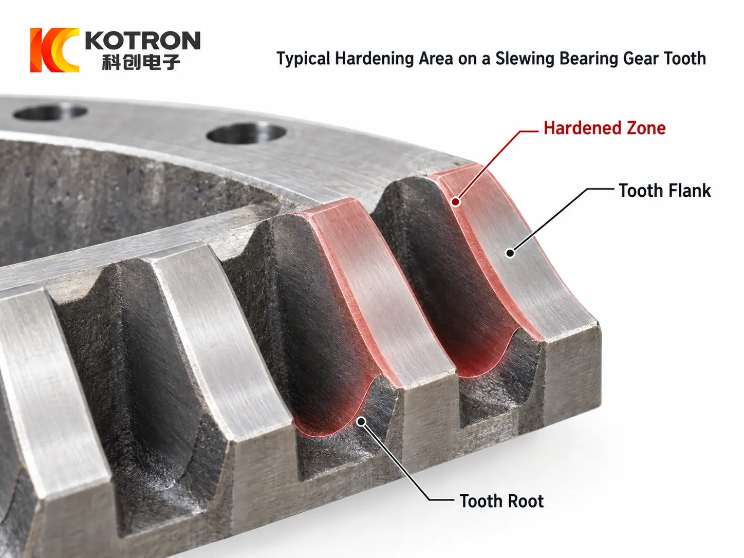
Tooth flank and tooth root hardening zones on a slewing bearing gear.
El tooth flank is the working surface that repeatedly meshes with the drive pinion. It is exposed to contact pressure, tooth wear and contact-fatigue damage such as pitting.
At the tooth root, bending stress is concentrated as torque is transferred through the tooth. Some applications therefore require the hardened zone to extend from the flank toward the root instead of treating the flank alone.
The appropriate hardening pattern depends on factors such as:
•Módulo de engranajes
•Tooth geometry
•Material
•Dureza superficial requerida
•Case depth or hardened depth
•Operating duty
•Core toughness requirements
Induction hardening is only one part of overall gear durability. Geometría del engranaje, correct meshing, lubricación, alignment and the condition of the mating pinion also affect service performance.
The equipment therefore has to be configured around a defined heat-treatment requirement rather than simply applying maximum hardness to the entire gear.
Ⅴ. How the Hardening System Is Configured
There is no single machine configuration suitable for every slewing bearing or slewing ring.
We evaluate three groups of information before determining the system layout.
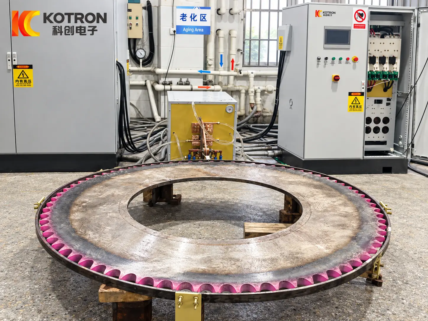
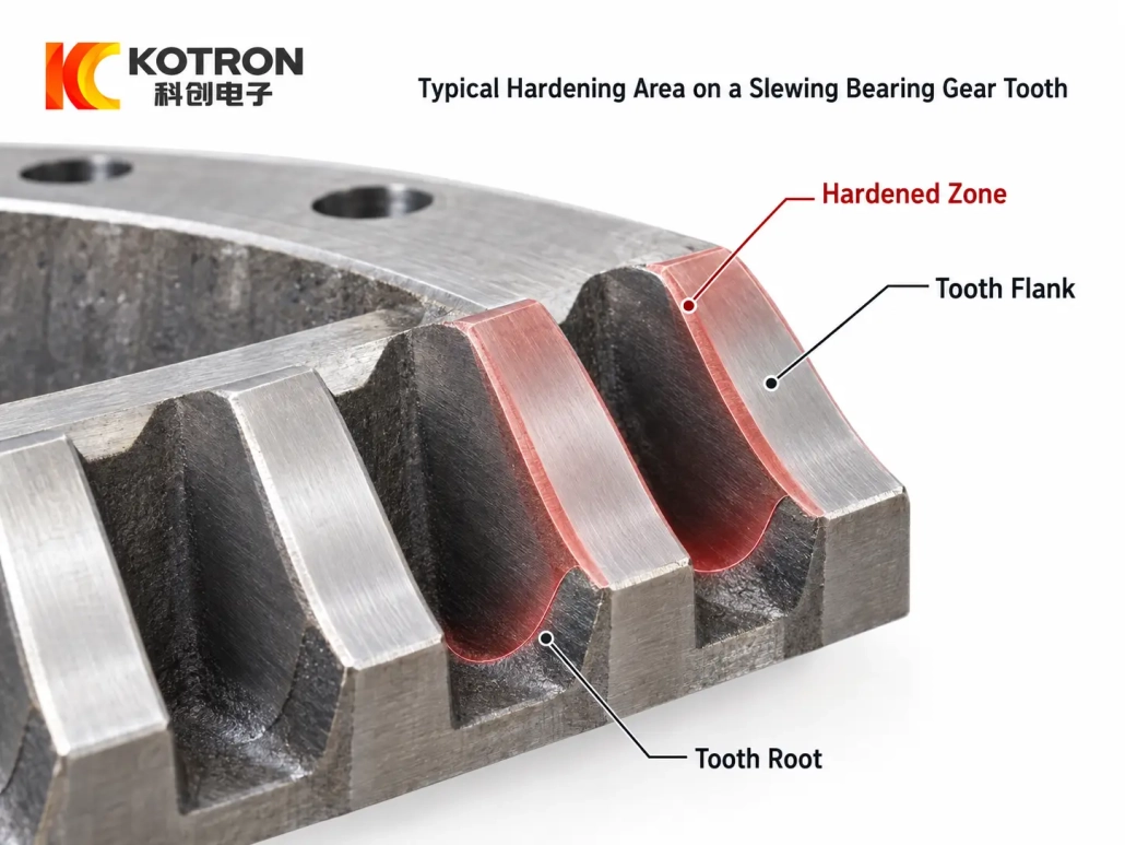
A slewing bearing workpiece on an induction hardening machine.
Pieza de trabajo
Typical workpiece information includes:
•Diámetro del engranaje
•Internal or external gear
•Módulo de engranajes
•Material
•Peso de la pieza
•Tooth geometry
•Dibujo de pieza
These factors affect workpiece support, machine dimensions, inductor access and movement.
Requisito de endurecimiento
The heat-treatment specification should identify:
•Área endurecida requerida
•Tooth flank only or flank + root
•Requisito de dureza superficial
•Profundidad del caso / hardened depth
•Tasa de producción requerida
Depending on the gear geometry and specified hardening zone, the processing approach may involve individual-tooth or tooth-contour hardening methods. The appropriate method should be selected from the actual gear rather than treated as a universal process for all slewing rings.
Configuración de la máquina
The final system may involve different combinations of:
•Estructura de la máquina
•Rotación de la pieza de trabajo
•Inductor positioning and movement
•Fuente de alimentación por inducción
•Disposición de enfriamiento
•Workpiece support
•CNC / control PLC
•Customized process programming
The machine and process are evaluated together. Changing the workpiece size or hardened zone can affect both the mechanical arrangement and induction setup.
Ⅵ. Applications in Excavators, Grúas y Equipo Pesado
Geared slewing bearings are used where a large structure has to rotate while carrying substantial load.
Excavators
On an excavator, the slewing bearing connects the upper structure with the undercarriage. A drive pinion meshes with the slewing gear to rotate the cab, engine, boom and upper frame relative to the tracks.
Normal operation involves repeated starting, stopping, reversing and repositioning.
These changing loads are transmitted through the gear teeth. The tooth flank therefore needs suitable wear and contact-fatigue resistance, while the root area must withstand repeated bending stress.
Cranes
A crane slewing system also uses the ring gear to transmit rotational torque, but the operating condition is different.
The upper structure may rotate under varying external loads, and the gear remains responsible for transferring the drive torque through repeated mesh contact. A properly specified hardening pattern supports the working surfaces of the teeth while retaining the material properties required below the hardened layer.
Similar geared slewing systems are also found in aerial work platforms, concrete pump trucks, mining equipment and other heavy rotary machinery.
The required hardening specification should still be determined from the individual machine duty rather than copied from another application.
Ⅶ. Gear Hardening vs. Raceway Hardening
A slewing bearing may contain more than one heat-treated working area, but gear hardening and raceway hardening are different processes.
Endurecimiento de engranajes focuses on the tooth flank, tooth root or another specified gear-tooth region that transmits torque through the drive pinion.
Raceway hardening treats the bearing track where the rolling elements carry contact loads.
The two processes require different inductors, motion paths and process settings.
For equipment developed specifically for the bearing track, consulte nuestra slewing bearing raceway hardening machine.
Ⅷ. Existing Machine Configurations
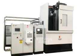
Machine capacity, allowable gear module, hardened depth, CNC system and mechanical structure depend on the selected equipment configuration and workpiece.
Rather than duplicate a specification table that applies only to one machine, this page covers the broader slewing bearing gear hardening solution.
Customers evaluating a specific internal-gear configuration can refer to our Máquina de Endurecimiento por Inducción de Engranajes Internos de Rodamiento de Doble Estación con Giro for detailed machine structure and technical specifications.
External-gear systems and other customized configurations can be evaluated separately from the workpiece drawing.
IX.. What We Need From Your Slewing Bearing
For a new slewing bearing gear induction hardening project, please provide as much of the following information as possible:
•Dibujo de pieza de trabajo
•Diámetro del engranaje
•Internal or external gear
•Módulo de engranajes
•Material
•Peso de la pieza
•Área endurecida requerida
•Dureza superficial requerida
•Profundidad de cementación requerida / hardened depth
•Tasa de producción
These details allow us to evaluate the inductor, patrón de endurecimiento, movimiento de la pieza de trabajo, machine structure, induction power and quenching arrangement as one system.
You do not need to determine the machine power or mechanical structure before contacting us. The workpiece drawing and heat-treatment specification are the more useful starting point.
Preguntas frecuentes
Haga clic en una pregunta para ampliar la respuesta.
What is the difference between internal and external slewing bearing gear hardening?
The gear position changes how the inductor approaches the teeth. External gear teeth sit on the outside circumference, so the inductor comes from the outside. Internal gear teeth sit on the inner circumference where access is restricted, requiring a different machine structure, inductor arrangement and motion path.
Can one machine harden both the tooth flank and the tooth root?
The machine is configured around the specified hardening zone. Tooth flank hardening treats the meshing surface, while flank-and-root hardening extends the zone toward the root where bending stress concentrates. The inductor and process are chosen from the drawing and heat-treatment requirement.
Do two slewing bearings with a similar outside diameter use the same process?
No necesariamente. Módulo de engranajes, geometría del diente, material, peso de la pieza de trabajo, required case depth and the position of the hardened zone all affect the machine and inductor design. The workpiece drawing is the starting point for equipment selection.
What information do I need to send for a technical proposal?
The workpiece drawing, gear diameter, internal or external gear, gear module, material, peso de la pieza de trabajo, área endurecida requerida, dureza superficial, profundidad del caso y tasa de producción. You do not need to determine machine power or mechanical structure first.
Is gear hardening the same as raceway hardening?
No. Gear hardening treats the tooth flank, root or another gear-tooth region that transmits drive torque. Raceway hardening treats the bearing track where rolling elements carry contact loads. They require different inductors, motion paths and process settings.
Configure a Machine Around Your Slewing Bearing
Send your workpiece drawing and heat-treatment specification. We will evaluate the inductor, patrón de endurecimiento, movimiento de la pieza de trabajo, machine structure and quenching arrangement together, then return a technical proposal for your gear.