
3 控制选择性感应淬火深度的行之有效的方法
在许多感应淬火应用中, only certain areas of a part need to be hardened—bearing journals, seal surfaces, 齿轮齿, 凸轮凸轮轴. Other areas must stay softer to maintain core toughness, reduce distortion, or meet assembly requirements. This is where selective induction hardening becomes essential. The goal is straightforward: deliver intense heat to a defined zone while keeping adjacent areas cool or only lightly heated.
The underlying physics of 感应加热 gives you a natural advantage here—heat is generated inside the metal itself, 不是从外部来源传输的. But turning that advantage into a precise, repeatable hardening pattern requires deliberate inductor design. For scanning hardening, you can adjust power and scan speed as the coil moves. 用于单次淬火, where the part and inductor stay stationary, the heating pattern must be built into the coil geometry from the start.
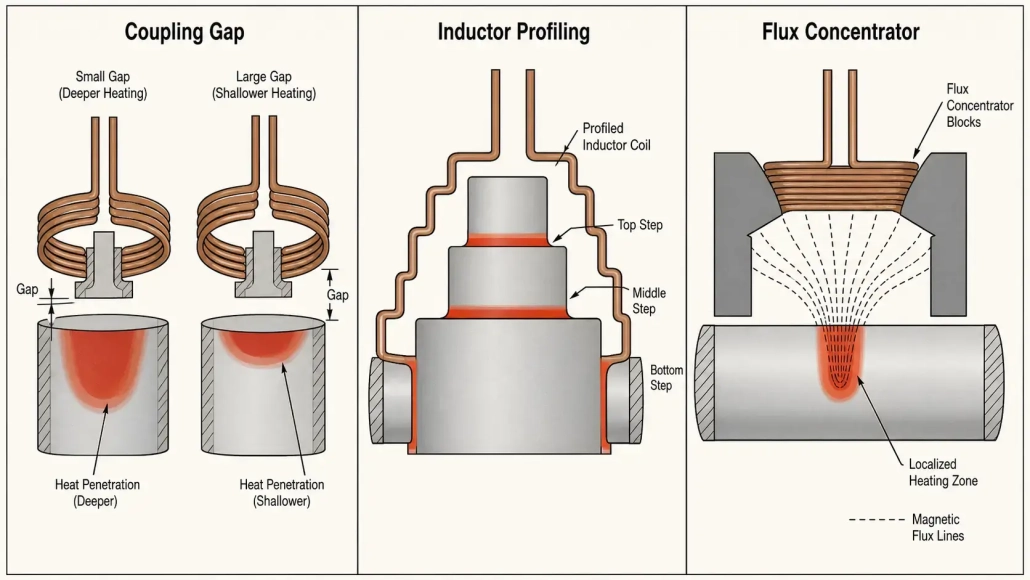
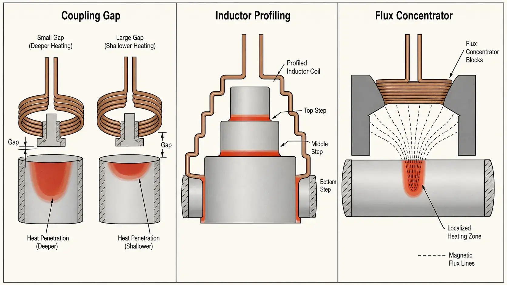
There are three primary design levers that control where heat goes and how deep it penetrates: 耦合间隙, inductor profiling, and flux concentrators. Each gives the engineer a different level of control. Used together, they can produce a hardening pattern that is accurate, stable, and well-matched to the part design.
| 1. 耦合间隙: 第一个杠杆 | 2. 感应器轮廓设计: 形状很重要 |
| 3. 磁通集中器: 精密控制 | 4. 如何结合三种方法 |
| 5. 扫描与单次淬火 | 6. 5 实用设计技巧 |
| 7. 要点 | 8. 常见问题解答 |
1. 耦合间隙 — 加热强度的第一个杠杆
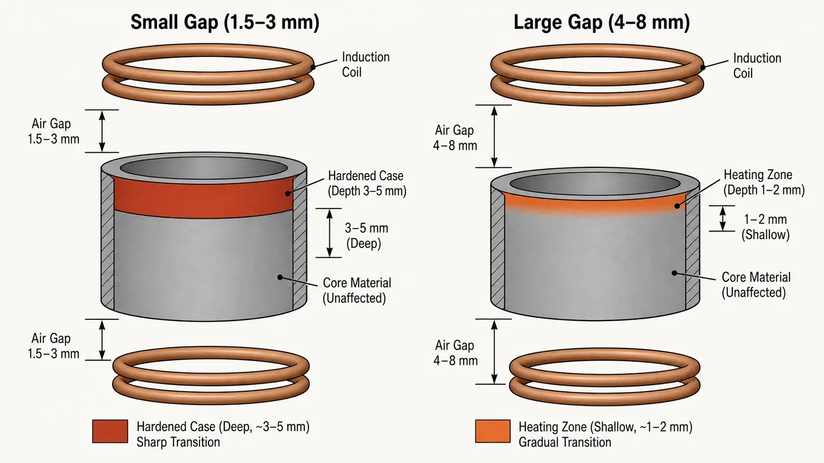
耦合间隙是感应器与工件表面之间的距离. 它是在中调节局部加热强度最简单快速的方法 selective induction hardening. 物理原理直接: 电磁耦合强度随距离迅速衰减. A smaller gap means stronger coupling and more induced current in the part. A larger gap means weaker coupling and less heat.
在实践中, coupling gap control follows a predictable pattern:
— 1.5–3 毫米间隙: Strong coupling, deeper case depth (3–5 毫米典型值), faster heating. Used for zones that need full hardening depth.
— 3–6 毫米间隙: Moderate coupling, shallower case (1–3 毫米). Used for transition zones or areas that need only surface treatment.
— 6–10 毫米间隙: Weak coupling, minimal or no hardening. Used to skip zones that must stay soft.
在工艺开发过程中, coupling gap adjustment is often the first tuning step. It requires no tooling changes—just repositioning the coil relative to the part. 然而, gap control alone has a practical limit: on complex geometries with shoulders, radii, or sudden cross-section changes, a uniform gap cannot produce a sharply defined heating zone. That is where profiling takes over.
2. 感应器轮廓设计 — 匹配线圈与工件
直筒形电感器无法从端到端均匀加热工件. 线圈中心产生的加热比边缘强,因为存在电磁边缘效应—磁场在电感器端部约束较小, 因此耦合效率在那里下降. 在简单的轴上, 这会产生桶形加热分布: 中间深硬化, 端部浅硬化. That is rarely what the part drawing calls for.
An inductor profile is a deliberate shaping of the coil to follow the workpiece contour. The profile can tighten the gap at the ends to compensate for edge losses, 在需要较少热量的区域打开间隙, 或围绕凸缘和台阶等特征进行轮廓处理. 结果是与零件几何形状匹配的加热模式,而不是与之对抗.
— 减少中心过热: 通过调整线圈轮廓, 你可以防止桶状形的模式,并使端到端的渗碳深度更平坦.
— 改善边缘加热: 线圈端的紧密耦合补偿了磁场强度的自然下降.
— 使淬火区匹配零件形状: 适用于阶梯轴, 带肩轴, 以及具有多个直径的零件, 轮廓设计可在几何形状变化时保持渗碳深度一致.
— 更一致地控制最终淬火深度: 良好轮廓设计的线圈可以减少生产过程中对功率的调整需求.
轮廓处理对于带有肩部, 台阶, 过渡, 或需要不同硬化级别的多个表面的零件尤其有价值. 应用如 内孔硬化 高度依赖轮廓处理, since the coil must conform to a confined ID geometry while producing a uniform case around the bore circumference.
3. 磁通集中器 — Precision When Gap and Profile Aren’t Enough
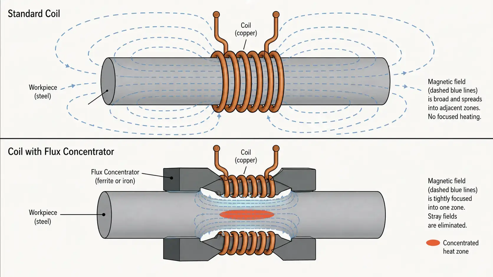
If coupling gap is the coarse adjustment and profiling is the shape adjustment, flux concentrators are the fine-tuning tool. A flux concentrator is a magnetic material placed on or near the inductor that redirects the magnetic field—essentially blocking it from areas you want to protect and focusing it into areas you want to heat. 它不会改变线圈的几何形状或零件的位置. 它改变了磁通实际上流向的地方.
通过适当设计的磁通集中器, 工程师可以同时控制三件事: 热量的传递位置, 每个区域的强度, 以及目标区域的温度均匀性. 当一个零件沿长度需要明显不同的硬化水平时,这使得磁通集中器不可或缺—例如, 例如一个轴,其带有硬化轴承颈部,旁边是柔软的花键部分.
The material choice for flux concentrators depends on the operating 频率范围:
— Laminated silicon steel: For low frequencies below 10 千赫. High magnetic permeability, low cost, but eddy-current losses increase rapidly above 10 千赫.
— 铁氧体: For medium frequencies from 10 kHz to roughly 100 千赫. Low electrical conductivity keeps eddy-current losses manageable, good permeability at mid-range frequencies.
— Soft magnetic composites (SMC): For higher frequencies above 100 千赫. Pressed powder materials with distributed air gaps, very low eddy-current losses, can be machined to complex shapes.
在许多 selective induction hardening 应用中, 磁通集中器提供的空间控制比仅靠间隙调整或轮廓设计能实现的要精细. 其代价是增加了设计复杂性和材料成本—但是对于硬化图案规范要求严格的零件, 它们通常是唯一可行的解决方案.
4. 如何结合三种方法
在生产硬化中, 最佳结果很少仅依靠一种方法. 每种杠杆有不同的强度, 并且它们按逻辑层级协同工作:
| 方法 | 控制精度 | 成本影响 | 最佳使用场景 |
|---|---|---|---|
| 耦合间隙 | 低–中 | 最小 | 广泛的强度调节, 工艺调整 |
| 感应器轮廓设计 | 中–高 | 中等 | 匹配零件轮廓, 减少边缘效应 |
| 磁通集中器 | 高 | 更高 | 精确的区域控制, 复杂的场形状设计 |
一个实际的设计顺序如下: 首先从耦合间隙开始,以设置工件的整体加热强度. 然后使用电感器轮廓匹配线圈形状与工件几何形状—补偿边缘效应, 遵循轮廓, opening up over areas that should stay cool. 最后, add flux concentrators for fine-tuning: directing stray flux away from protected zones and concentrating it into the target area.
When these three tools are deployed together, the inductor delivers heat exactly where it is needed—and keeps it away from areas that must remain unhardened. The process becomes more stable because each method addresses a different source of variation: gap handles coupling strength, profiling handles geometry matching, and flux concentrators handle field shaping.
5. Scanning Hardening vs Single-Shot Hardening
The choice between scanning and single-shot affects how much of your zone control must be built into the coil versus how much can be handled by the process parameters. In scanning hardening, the inductor moves along the part during heating. You can vary power, 扫描速度, and dwell time as the coil passes through different zones. This dynamic control makes it easier to produce varying case depths along a single part without complex coil geometry.
在单次淬火中, the inductor and workpiece remain stationary. 整个加热模式在通电之前就已经确定—通过线圈的几何形状, 每个点的耦合间隙, 以及安装的任何磁通集中器. 热循环过程中没有实时调整. 因此, 一次性应用更依赖于从一开始就高质量的线圈设计. 上述描述的三个设计杠杆—间隙, 轮廓设计, 磁通集中器—在一次性应用中不是可选的; 它们是主要的控制手段.
If your application requires precise local hardening and your production volume justifies single-shot tooling, the inductor should be designed with the same level of care as the power supply and process settings. For a deeper comparison of scanning and single-shot systems, 参见我们的指南 如何选择感应淬火系统.
6. 5 Practical Design Tips for Better Zone Control
— 1. Do not rely on power alone. Power level controls how much total energy goes into the part, but it cannot fix a poorly designed inductor. 如果磁场形状不正确, 增加功率通常会使问题更严重,因为会使本已加热最快的区域过热.
— 2. 及早检查零件几何形状. 工件的形状—截面变化, radii, 肩部, 键槽—对加热均匀性有重大影响. 在线圈设计开始前应识别出会集中或分散磁场的特征, 而不是在工艺试验中才发现.
— 3. 系统地测试间隙变化. 一个 1 耦合间隙的毫米变化可以产生可测的硬化深度差异. 在设置过程中, 以受控增量变化间隙并记录结果. 这些数据成为生产公差的基础.
— 4. 首先使用轮廓分析以减少边缘效应. 在添加磁通集中器之前, 优化线圈轮廓. 轮廓分析通常是提高端到端均匀性的最快方法, 并且它避免了集中器带来的额外材料成本和装配复杂性.
— 5. 当需要更严格的控制时再添加磁通集中器. If the heating pattern is still too broad or uneven after optimizing gap and profile, flux concentrators can sharpen it. They are particularly effective when you need a hard transition boundary between a hardened zone and an adjacent soft area—例如, within a few millimeters of a snap-ring groove or oil hole.
The common thread across all five tips: inductor design drives zone control. 这些 电源 provides the energy, but the coil determines where that energy actually goes. For more on what can go wrong when zone control is inadequate, our guide to common 感应淬火缺陷 covers the symptoms—uneven case depth, 软点, and pattern shift—that often trace back to inductor design.
要点
Selective induction hardening is about putting heat in the right place and controlling how deep that heat goes—nothing more, nothing less. For localized hardening applications, the three most useful design levers are coupling gap for broad intensity control, inductor profiling for geometry matching, and flux concentrators for precision field shaping. Used together in sequence—gap first, then profile, then concentrators—they allow you to create a heating pattern that is accurate, stable, and well-matched to the part drawing. If you need to harden only specific zones of a workpiece, design the inductor as carefully as you select the power supply and process settings.
常见问题解答
问: What is selective induction hardening?
一个: Selective induction hardening means heating and quenching only specific zones of a part—such as bearing journals, seal surfaces, or gear teeth—while leaving adjacent areas unhardened. 这可以在非关键区域保持韧性和延展性,同时在易磨损或易疲劳的区域实现所需的硬度.
问: 控制硬化深度最简单的方法是什么?
一个: 耦合间隙是最容易的起点. 较小的间隙 (1.5–3 毫米) 增加电磁耦合并产生更深的硬化层. 较大的间隙 (3–10 毫米) 削弱耦合并产生较浅或没有硬化. 间隙调整不需要更改工具,并且可以在工艺开发过程中快速测试.
问: 用于磁通集中器的材料有哪些??
一个: Three material families are commonly used: laminated silicon steel for low frequencies (以下 10 千赫), ferrite for medium frequencies (10–100 千赫), and soft magnetic composites (SMC) for high frequencies (多于 100 千赫). The choice depends on operating frequency, required precision, 以及零件几何形状.
问: Is scanning hardening easier to control than single-shot hardening?
一个: 一般是的. Scanning hardening allows you to adjust power and scan speed dynamically as the coil moves across different zones. Single-shot hardening produces the entire heating pattern in one stationary cycle, so coil design—间隙, 轮廓设计, and flux concentrators—determines the result. Single-shot demands more upfront engineering, but it can achieve higher throughput for high-volume production.
Need a Custom Coil for Selective Hardening?
Tell us about your part geometry, target zones, 渗层深度要求, 以及生产量. We’ll help you design an inductor that delivers heat exactly where you need it.


