Szczelina cewki do części w nagrzewaniu indukcyjnym: Dlaczego zmienia to wyniki ogrzewania
The distance between an induction coil and the workpiece is more than a mechanical clearance. It is part of the induction heating process.
Changing the przerwa między cewką a częścią changes the electromagnetic coupling between the inductor and the workpiece. That can affect heating rate, heat distribution and, in heat-treatment applications, the position and shape of the hardened area.
The objective is not to place the coil as close as physically possible. The spacing needs to suit the part, inductor and process while remaining controllable during production.
2. Why Coupling Distance Changes Heating
3. Why the Smallest Gap Is Not Always the Best Choice
4. Uneven Gap, Runout and Workpiece Geometry
5. Coupling Distance Should Not Be Adjusted by Itself
6. What Should Be Checked in Production?
7. Coil-to-Part Gap Is a Process Variable
1. What Is the Coil-to-Part Gap?
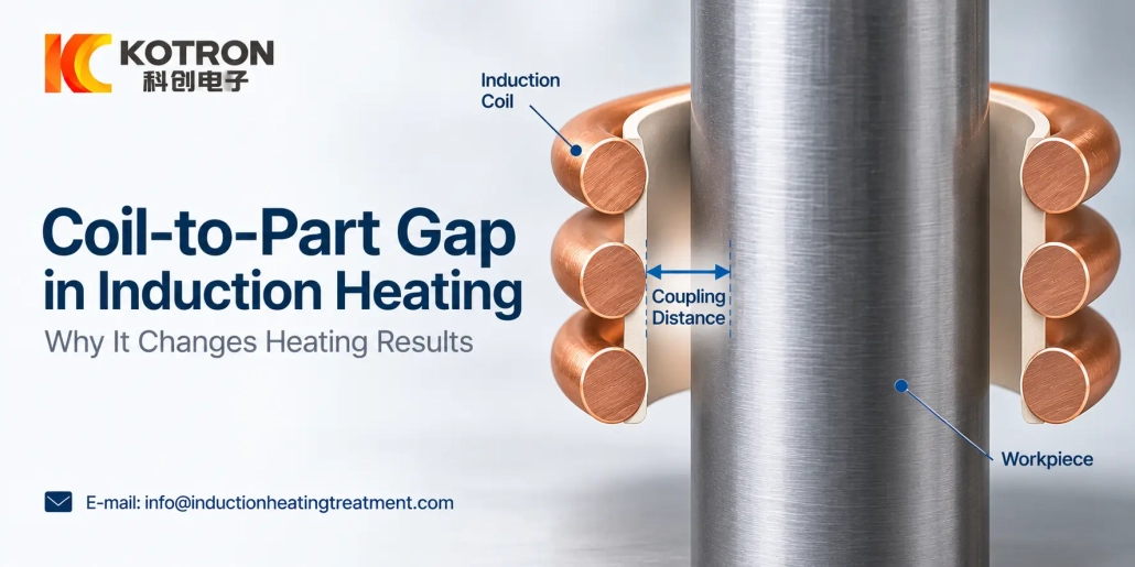
The coil-to-part gap, also referred to as odległości sprzężenia, odległość cewki do obrabianego elementu czy luka sprzężenia, is the spacing between the active portion of the cewka indukcyjna and the surface being heated.
A relatively small gap is commonly described as tight coupling, while a larger gap gives looser coupling.
This distance matters because the magnetic flux linking the coil and workpiece decreases as the spacing increases. Radyne describes coupling specifically as the relative gap between the inductor and the workpiece and notes that closer coupling generally increases the concentration of magnetic flux at the workpiece surface. Radyne: About Inductors
The required distance cannot be selected from the gap alone. Geometria cewki, geometria części, frequency and the required heating pattern also affect the result.
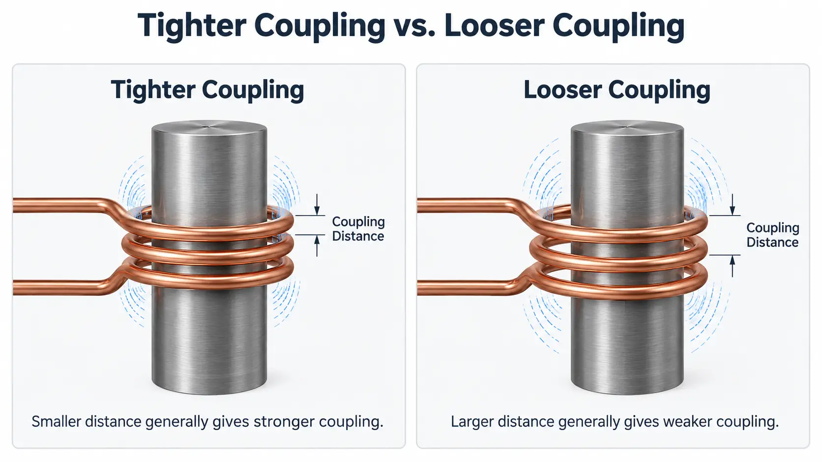
Coil-to-part gap: the coupling distance between the inductor and the workpiece surface.
2. Why Coupling Distance Changes Heating
Moving the workpiece closer to or farther from the active coil changes how strongly the two are electromagnetically coupled.
Closer coupling generally increases the heating response. Increasing the distance usually reduces coupling and can also change how closely the heated area follows the shape of the inductor. Radyne: About Inductors
W zależności od zastosowania, a change in spacing may affect:
•szybkość nagrzewania
•local heat distribution
•width or position of the heated zone
•time required to reach the required condition
•the hardening pattern in induction heat treatment
This is one reason nominal power and heating time do not describe the complete process. Two setups using the same electrical settings can behave differently if their coil geometry or actual coil-to-workpiece relationship is different.
3. Why the Smallest Gap Is Not Always the Best Choice
Tight coupling can increase the heating rate, but reducing the distance as far as possible is not a useful general design rule.
Production equipment also has to accommodate mechanical variation. The clearance may need to allow for workpiece tolerances, runout, positioning variation and, tam, gdzie ma to zastosowanie, rozszerzalność cieplna podczas ogrzewania.
Fixture and handling accuracy matter as well. A gap that works with one perfectly positioned sample may provide too little clearance when normal production variation is introduced.
Ambrell makes the same distinction: although moving the workpiece closer to the coil can increase heating rate, practical production systems normally retain an air gap to accommodate tolerances in the part, coil and handling fixture. Ambrell: Odległość sprzężenia
The useful target is therefore a suitable and repeatable coupling distance, not simply the smallest achievable distance.
There is no universal induction coil gap that is correct for every workpiece or process.
4. Uneven Gap, Runout and Workpiece Geometry
A nominal gap can be correct while the actual coil-to-part relationship is still poor.
Na przykład, if a shaft is slightly off-center inside a surrounding inductor, one side is closer to the coil than the other. Runout during rotation can make that relationship change continuously during the heating cycle.
The same issue can appear in different forms with other geometries.
Round parts
Concentricity and runout affect the spacing around the circumference. Mechanical positioning can therefore influence the heating pattern even when the electrical settings remain unchanged.
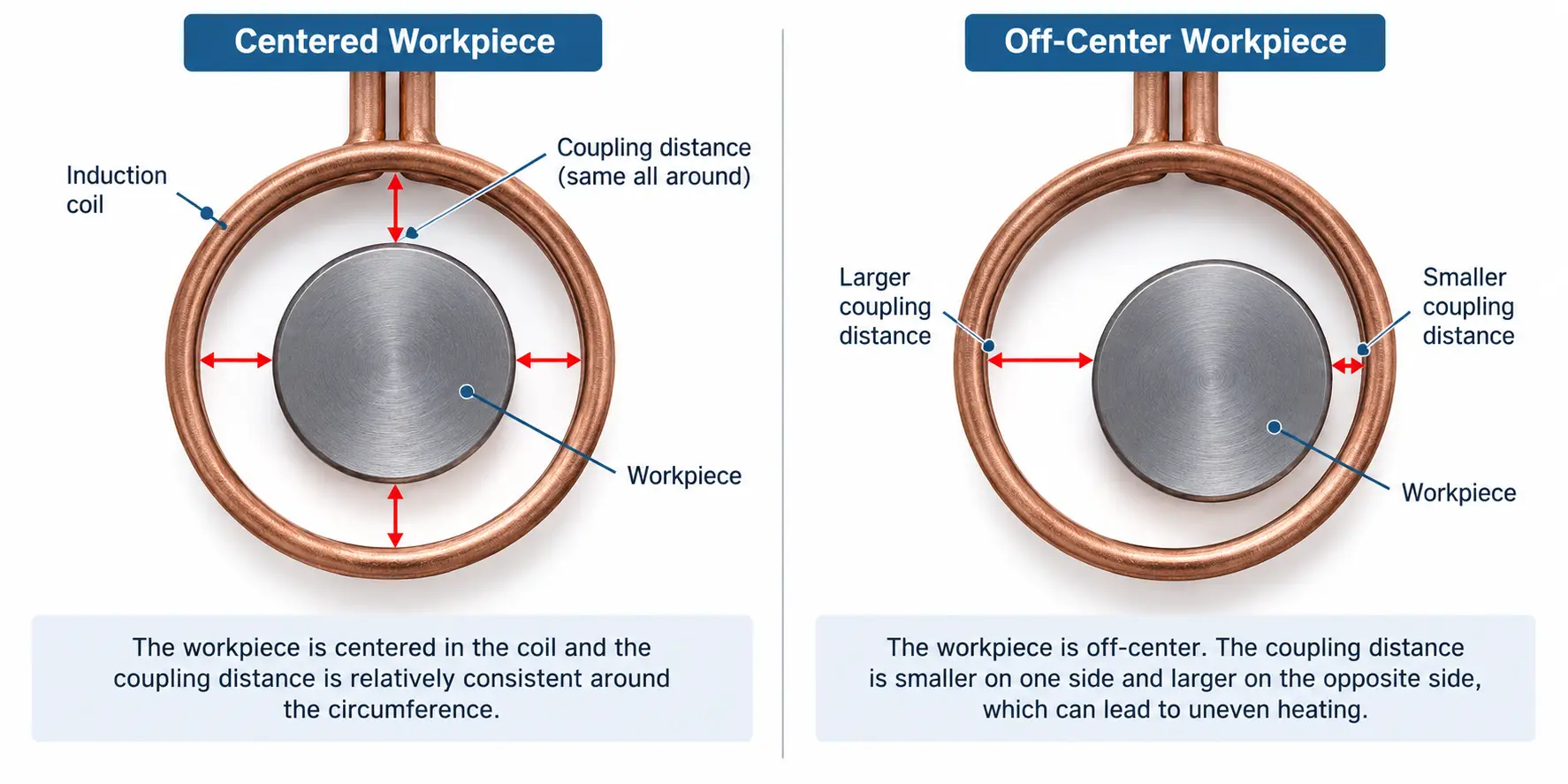
Centered vs. off-center: an off-center workpiece changes the coil-to-part gap around the circumference.
Profiled, square and rectangular parts
Tooth tips, korzenie, flat faces, corners and other features do not necessarily sit at the same distance from the active coil surface. The inductor has to be developed around the actual geometry rather than one nominal outside dimension.
Scanning applications
A satisfactory gap at the start of a scan does not prove that it remains satisfactory over the full travel. Workpiece straightness, wsparcie, machine alignment and fixture condition can change the relationship farther along the part.
GH Induction likewise identifies distance between the inductor and part as a factor affecting coupling and induced heating. Indukcja GH: Projekt cewek
When an established process begins to show nierównomierne ogrzewanie, a shifted hardening pattern or circumferential variation, checking the actual coil-to-workpiece position can therefore be as important as checking the power setting.
5. Coupling Distance Should Not Be Adjusted by Itself
Moving the coil closer is not a universal correction for slow or uneven heating.
Coupling works together with other process variables, w tym:
•geometria cewki indukcyjnej
•częstotliwość robocza
•moc
•czas nagrzewania
•ruch przedmiotu obrabianego
•part geometry and material
Radyne notes that both częstotliwość and coupling influence how closely the heated pattern follows the coil. Radyne: About Inductors
Changing the gap on an established process can therefore change more than heating speed. The resulting heating or hardening pattern should be checked rather than assuming the previous settings remain equivalent.
Not every difference in spacing is an error, either. Coil designers can deliberately change local coil spacing or coupling to influence the heating pattern. Ambrell describes adjustment of coil turns, spacing and coupling as methods used to shape heat distribution. Ambrell: Induction Coil Design Guide
The distinction is whether the variation is intentional and developed as part of the inductor design, or caused unintentionally by runout, poor positioning, coil movement or fixture wear.
6. What Should Be Checked in Production?
When heating results change without an obvious change in the electrical recipe, the mechanical relationship between the coil and workpiece deserves attention.
Przydatne kontrole obejmują:
Pozycja przedmiotu obrabianego
Confirm that the part is seated and located correctly in the fixture.
Runout and straightness
Check whether the workpiece moves closer to and farther from the coil during rotation or scanning.
Inductor position and condition
Look for movement, deformation or damage that may have changed the spacing.
Fixture condition
Wear or looseness in locating components can shift the workpiece even when the machine program has not changed.
Clearance along the scan path
For long parts, inspect the coil-to-workpiece relationship over the complete heated or hardened length rather than at only one position.
For repeat production, maintaining the intended spatial relationship between the coil and part is more useful than treating the gap as a one-time setup dimension.
7. Coil-to-Part Gap Is a Process Variable
The coil-to-part gap affects electromagnetic coupling, but there is no single distance that should be applied to every induction heating process.
Closer coupling can increase the heating response, while excessive spacing can weaken the interaction between the coil and workpiece. Jednocześnie, the system needs enough practical clearance for the real part, fixture and machine movement.
The engineering question is therefore not:
How close can the coil be placed?
Jest:
What coil-to-workpiece relationship produces the required heating pattern and can be maintained during production?
That answer depends on the part geometry, inductor design and process requirements.
Klucz na wynos
The coil-to-part gap is a process variable, not a one-time setup dimension.
Closer coupling raises the heating response, but the spacing must still accommodate part, fixture and machine variation.
The right gap produces the required heating pattern and stays repeatable in production.
Często zadawane pytania
Kliknij pytanie, aby rozwinąć odpowiedź.
+ Should the coil be placed as close to the part as possible?
Niekoniecznie. Closer coupling increases the heating response, but production systems normally keep an air gap to accommodate part tolerances, runout and fixture variation. The target is a suitable and repeatable coupling distance rather than the smallest one.
+ Does a smaller gap always speed up heating?
A smaller gap generally strengthens coupling and can raise the heating rate, but it also changes how closely the heated area follows the coil shape. Spacing has to work together with frequency, power and part geometry, so it is not an independent speed control.
+ Why did my heating become uneven when the electrical settings did not change?
The mechanical relationship between the coil and workpiece may have changed. Check workpiece position, runout and straightness, inductor condition, fixture wear and the clearance along the full scan path.
+ Is there one correct coil-to-part gap for every workpiece?
Nie. The required spacing depends on the part geometry, projektowania induktorów, frequency and the required heating pattern. It should be developed and verified for the actual application rather than copied from another part.
Not Sure About Your Coil-to-Part Gap?
Send us your part details and current process, and we can help evaluate the coil-to-workpiece relationship for your application.