
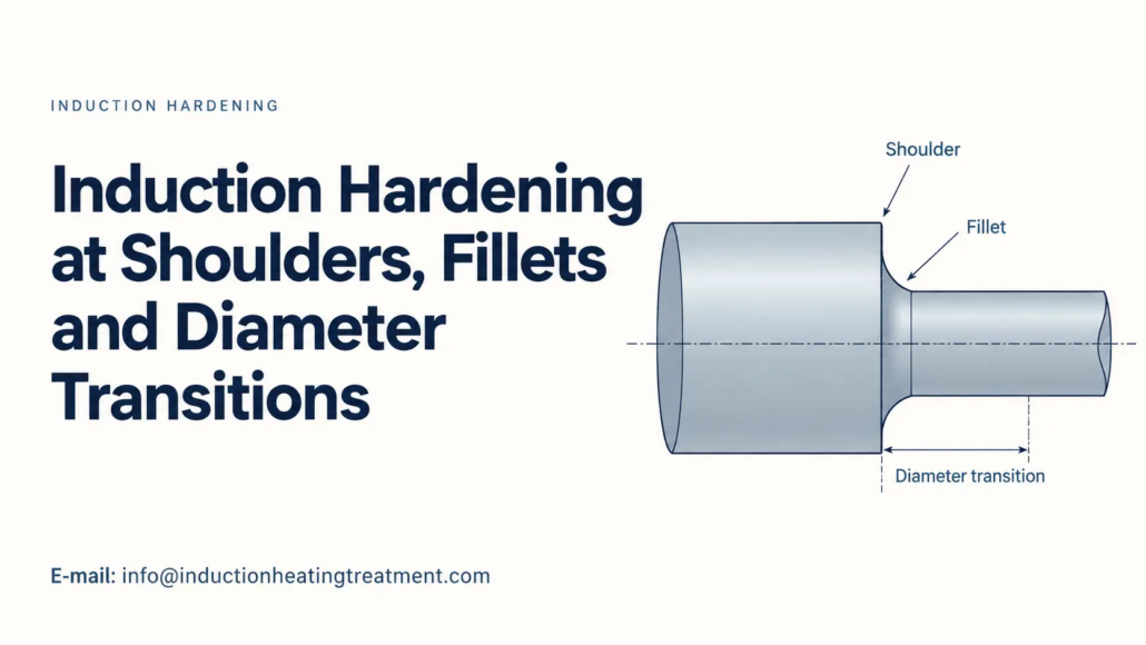
Tempra ad induzione sulle spalle, Raccordi e transizioni di diametro
Why Stepped Shaft Geometry Changes Local Heating and Hardened Case Patterns
Induction hardening a stepped shaft presents challenges that are less pronounced on a uniform cylindrical surface. Shoulders, fillets and diameter transitions change the local electromagnetic coupling and heating distribution, which can affect the depth and shape of the hardened case.
One difficulty is obtaining sufficient hardening at a fillet without overheating the adjacent shoulder. Understanding how these neighboring regions respond to induction heating is essential when the specified hardened case must follow a change in shaft diameter.
2. How Diameter Transitions Change the Hardened Case Pattern
3. How Inductor Design and Hardening Method Affect the Transition
4. How to Evaluate Hardening Results at Shoulders and Fillets
1. Why Shaft Shoulders and Fillets Heat Differently
A straight cylindrical shaft provides a relatively consistent surface geometry for a properly positioned induction coil. At a diameter transition, the surface changes direction, altering the induced-current paths and their relationship with the inductor.
The resulting heating differences involve more than variations in coil-to-part distance.
Current distribution near shaft shoulders
At geometric discontinuities, electromagnetic edge and end effects can modify the distribution of induced current. Depending on the direction of current flow and the inductor configuration, certain regions of a projecting shoulder may experience concentrated heating.
Frequenza, shoulder geometry and inductor position influence where this concentration occurs. Heat conduction into the surrounding steel also affects the local temperature, so the region receiving the greatest electromagnetic power density is not necessarily the hottest throughout the heating cycle.
This becomes important when a shaft shoulder lies immediately beside a fillet that must also be hardened.
Why the fillet may receive less heat
The fillet forms a curved transition between two shaft diameters. Its recessed geometry can make it more difficult to heat than the neighboring cylindrical surface or projecting shoulder.
In some induction-hardening arrangements, the induced-current distribution favors the shoulder while less energy reaches the fillet root. The fillet may then develop a shallower austenitized region, even though the adjoining shaft surface reaches the intended heating condition.
Increasing overall power can make this imbalance worse. The fillet may receive additional heat, but the shoulder can become excessively hot before the required austenitized depth is established at the fillet.
The challenge is to change the local distribution of heating rather than simply increase the total energy supplied.
Dr. Valery Rudnev discusses these geometry-related difficulties in Equipment Selection for Induction Hardening: Tempra singola, Part 1, including the different heating responses that can occur around shoulders, fillets and undercuts.
2. How Diameter Transitions Change the Hardened Case Pattern
The hardened case pattern describes the location and shape of the hardened region. On a stepped shaft, that region may need to extend along a cylindrical bearing surface, through a fillet and toward a shoulder.
A process that produces an acceptable case on the main shaft diameter may still leave the transition inadequately hardened.
Diameter changes affect the heating conditions
Nell'indurimento della scansione, an inductor moves relative to the shaft along the required heating path.
If the shaft has substantially different diameters, an inductor that clears the larger section may operate with a greater coupling gap around the smaller section. This changes the local electromagnetic coupling and can influence the heating rate.
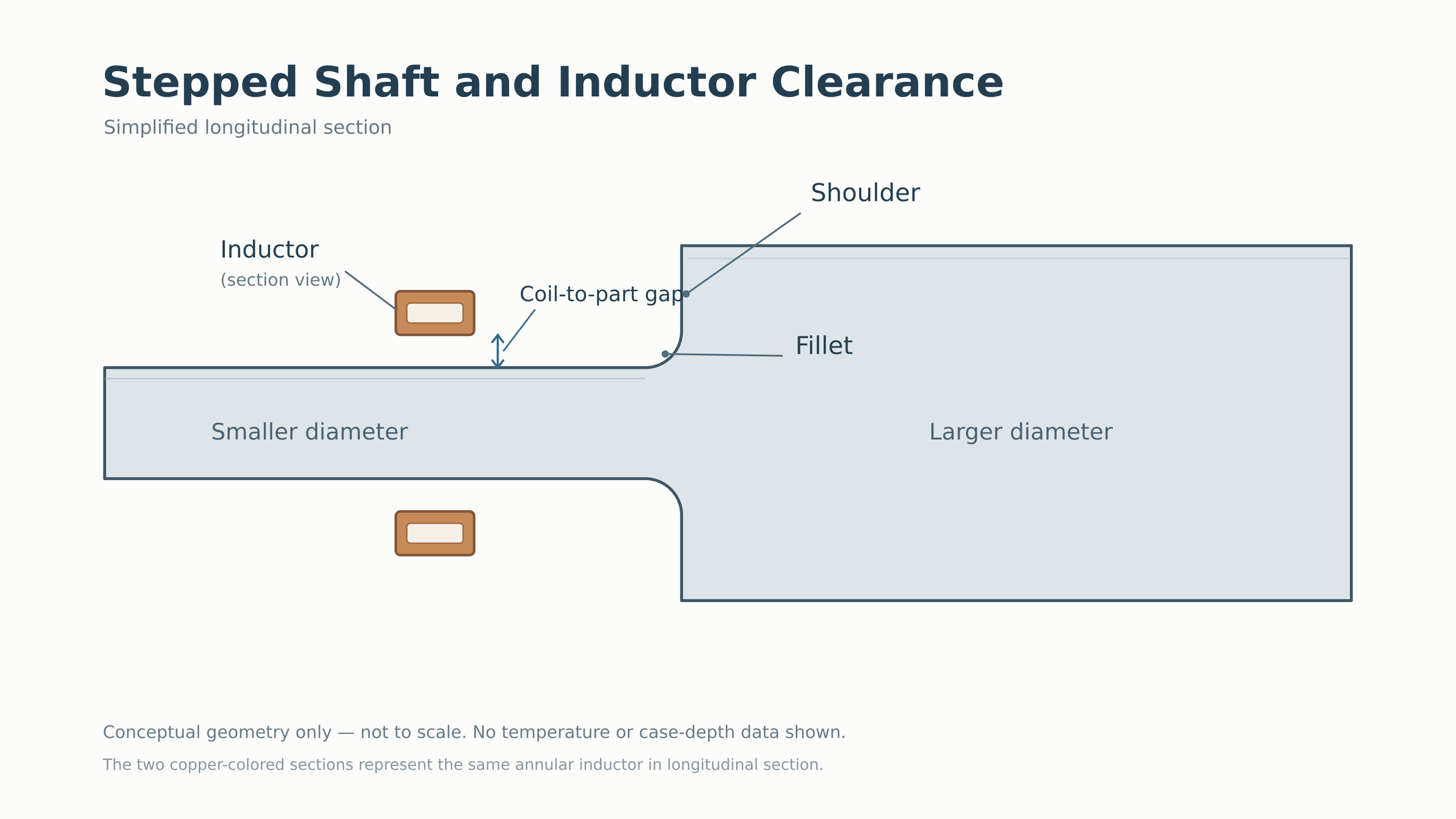
Near a shoulder, the inductor may interact with both the cylindrical surface and the radial face of the transition. Differences in section geometry and heat conduction further affect the temperature distribution.
Consequently, the same programmed power and scan speed may not produce the same heating exposure at every position along a stepped shaft.
Austenitized depth is not the same as effective case depth
The intended region must be sufficiently austenitized before quenching can produce the required martensitic structure.
If the fillet is not adequately austenitized at the specified depth, the final hardened case will be limited there, regardless of how effectively the surface is quenched.
Tuttavia, adequate austenitization does not by itself establish the final hardness profile. The steel’s temprabilità and local cooling conditions determine how the heated region transforms.
Shaft geometry can also affect quenchant access. A shoulder may redirect spray flow or create a region where direct impingement differs from that on an exposed cylindrical surface.
These effects need to be distinguished when investigating insufficient case depth near a transition. A shallow case can reflect inadequate heating, an unsuitable quenching response or a combination of both.
The case must follow the drawing, not an assumed uniform depth
A stepped shaft may have different hardening requirements for the shaft body and fillet. Some designs require the hardened region to extend through the fillet; others specify where hardening must stop.
Di Fluxtrol Ottimizzazione degli induttori di tempra Axle-Scan examines an axle application with separate requirements for the shaft body and fillet region. The example illustrates why case-pattern development must begin with the component’s specified hardened geometry.
A hardness measurement taken on the straight shaft surface cannot establish whether the fillet meets its own case-depth requirement.
3. How Inductor Design and Hardening Method Affect the Transition
Consider a stepped shaft that develops sufficient case depth along its main bearing surface but remains underhardened at the fillet. Increasing the heating power raises the temperature of the entire region, yet the shoulder begins to overheat before the fillet meets its requirement.
This is primarily a problem of where electromagnetic energy is delivered.
Changing the heating distribution
A profiled inductor may help direct more heating toward the fillet without applying the same increase to the adjoining shaft surface.
Its shape and position must account for the larger shaft diameter, required clearance and the local current distribution. Magnetic flux concentrators may also be used in certain inductor designs to modify the heating pattern.
Such changes need to be evaluated together. Improving coupling near the fillet can alter heating at the shoulder or another part of the transition.
Operating frequency also influences current distribution and penetration. Its effect depends on the inductor arrangement and workpiece geometry, so frequency alone is not a reliable adjustment for every fillet-heating problem.
The scan-hardening sequence
Nell'indurimento della scansione, the position of the transition relative to the moving heating zone matters.
For a fillet near the beginning of a scan, the initial heating period may influence how much energy reaches the curved region before the inductor moves along the shaft.
Depending on the arrangement, changes to the initial heating sequence, inductor profile or local heating exposure may improve the case pattern.
Tuttavia, an adjustment that increases fillet case depth may also extend hardening farther along the shoulder or adjoining shaft than intended.
Fluxtrol’s axle-scan study provides an example of geometry-specific inductor development, where heating of the fillet and neighboring shaft surface had to be considered together.
When single-shot hardening is worth considering
Indurimento a colpo singolo heats the intended region without progressively scanning a short heating zone along its length. This can be useful for some stepped shafts with pronounced shoulders or diameter changes.
The induced-current paths in many single-shot arrangements differ from those in conventional scanning systems. That difference can provide another way to distribute heating around the transition.
Whether this approach is suitable depends on the length of the hardened region, shaft geometry, required case pattern and quenching arrangement. An appropriately developed scanning process may remain the better option for other components.
The choice should follow the hardening requirements rather than an assumption that one method handles all stepped shafts more effectively.
Un 2021 study on induction heating of a stepped shaft investigated a specific configuration in which localized temperature excess at the shoulder and insufficient austenitization near the fillet were addressed through optimization of the heating system and operating conditions.
The study demonstrates the value of evaluating the transition as a whole, rather than correcting the fillet and shoulder separately.
4. How to Evaluate Hardening Results at Shoulders and Fillets
Inspection of a stepped shaft should establish whether the hardened case follows the required geometry and reaches the specified depth at each critical location.
Checking surface hardness only on the straight cylindrical section can overlook an incomplete case at the fillet.
Identify the required hardened region
The drawing should establish where hardening must begin and end, whether the fillet requires full coverage and what hardness or effective case-depth criteria apply.
Measurement location and direction are particularly important at a curved fillet.
A radial case-depth measurement from the adjacent cylindrical surface does not necessarily represent the hardened depth through the fillet itself. Where a specific measurement direction is required, inspection should follow that definition.
Use the case pattern to guide the investigation
The distribution of the hardened region can help identify which process conditions deserve attention.
| Risultato osservato | First Areas to Examine |
|---|---|
| Adequate case depth on the shaft body but insufficient depth at the fillet | Local heating exposure, austenitization at the fillet and quenching response |
| Excessive hardened depth near the shoulder | Local electromagnetic heating distribution and the extent of austenitization |
| Different case patterns across diameter changes | Geometria dell'induttore, coupling conditions and heating sequence |
| Acceptable surface hardness but incomplete hardening through the transition | Hardness-depth distribution and coverage at the specified locations |
These observations guide the investigation; they do not establish a cause by themselves.
Se necessario, a prepared cross-section and hardness measurements at the specified positions can show whether the hardened case follows the required transition.
Detailed procedures for hardness and case-depth evaluation are covered separately in Come ispezionare le parti temprate ad induzione.
Verify the surrounding region after an adjustment
Correcting an underhardened fillet can change the result at the adjacent shoulder or shaft body.
After adjusting the inductor position, heating sequence or other process conditions, the revised case pattern should be examined across the complete transition.
Per la produzione, the process must also tolerate the expected variation in workpiece positioning and material condition without moving the hardened region outside its specified boundaries.
The practical objective is a hardened case that follows the intended shaft geometry. On stepped shafts, achieving that result requires local heating distribution, quenching response and inspection locations to be considered together—not just the hardness obtained on the main cylindrical surface.
Chiave da asporto
Induction hardening at shoulders, fillets and diameter transitions depends on local current distribution more than total power. The hardened case must follow the drawing at every critical location, and a shallow fillet can hide behind an acceptable shaft-body reading. Correct the transition as a whole, then re-inspect the full case pattern.
Domande frequenti
Fare clic su una domanda per espandere la risposta.
Why is the fillet harder to harden than the shaft body?
The fillet’s recessed, curved geometry receives less induced-current density than the neighboring cylindrical surface or projecting shoulder. It can stay under-austenitized even when the adjoining shaft reaches the intended temperature, leaving a shallow case at the fillet root.
Does turning up the power fix an underhardened fillet?
Raramente. Higher total power adds heat everywhere, so the shoulder usually overheats before the fillet reaches the specified austenitized depth. The fix is to change where energy is delivered — through inductor profile, concentratori di flusso, position or frequency — rather than how much is applied.
When should I consider single-shot hardening instead of scan hardening?
Single-shot can help on stepped shafts with pronounced shoulders or diameter changes, because its induced-current paths differ from a scanning setup and may cover the transition more evenly. It depends on the hardened length, shaft geometry, required case pattern and quenching arrangement.
How should I inspect hardness at a fillet?
Follow the measurement locations and direction on the drawing. A radial reading from the adjacent cylinder does not represent depth through the curved fillet, and surface hardness on the straight section can miss an incomplete case. A prepared cross-section with hardness checks at the specified positions is the reliable method.
Need a Hardened Case That Follows Your Shaft Geometry?
Send us your stepped-shaft drawing and hardening specification, and we will help develop an inductor and process that hardens shoulders, fillets and diameter transitions to the required case pattern.


