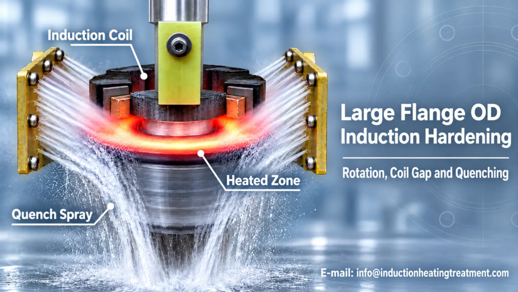
تصلب الحث OD شفة كبيرة: الدوران, فجوة الملف والتبريد
كيفية دوران الشغل, Inductor Positioning and Spray Quenching Affect Circumferential Hardening Uniformity
Large flange OD induction hardening requires coordinated control of workpiece rotation, induction heating and quenching. When a localized induction coil treats the outer diameter progressively, variations in surface speed, coil-to-part gap or cooling conditions can affect hardness and case depth around the circumference.
The main challenge is to produce the specified hardened region consistently, particularly on large components where workpiece runout, positioning and the start/end of the hardening path may introduce local variations.
2. Workpiece Rotation and Surface Speed
3. Coil Positioning, Gap and Radial Runout
4. Spray Quenching and Circumferential Hardening Continuity
5. How to Evaluate Hardening Uniformity
1. How Large Flange OD Induction Hardening Works
Large flange OD induction hardening is a surface heat-treatment process applied to the outside cylindrical surface of a suitable steel flange or flanged component.
An induction coil heats the selected surface region to the temperature required for austenitization. Quenching then provides the cooling needed to develop a hardened microstructure.
The objective is to produce the specified hardness and hardened-layer depth within the required OD region, rather than hardening the entire component.
ثم يقوم القطر الخارجي (القطر الخارجي) must be distinguished from the flange face, bore or adjacent shoulders. These surfaces have different geometries and may require different inductor arrangements.
Material suitability must also be established. Not every flange material can achieve the required hardness through conventional induction transformation hardening.
Rotational and scanning arrangements
Several heating arrangements are possible:
Rotating workpiece: The flange rotates past a localized induction coil.
Moving inductor: The inductor travels around the workpiece while the flange remains stationary or undergoes auxiliary motion.
التصلب بضربة واحدة: The required region is heated without progressively scanning the circumference.
These arrangements do not have identical heating and quenching requirements.
For a rotating-workpiece system, the flange OD passes through a localized heating zone. Each surface location receives heat as it moves relative to the inductor, followed by quenching according to the machine arrangement.
The resulting hardening pattern depends on the relationship between surface movement, التعرض للتدفئة, coil positioning and cooling.
The following sections focus on this rotational method, which illustrates the particular challenges of treating a large circumference with a localized inductor.
2. Workpiece Rotation and Surface Speed
Rotation determines how the flange surface moves through the heating zone. ومع ذلك, rotational speed in revolutions per minute (RPM) does not directly represent the speed of the outer surface.
RPM versus circumferential surface speed
For a circular workpiece:
v = πDn
أين:
— v = circumferential surface speed (م/دقيقة)
— D = outside diameter (م)
— n = rotational speed (rev/min)
At the same RPM, a larger flange has a higher circumferential surface speed.
For a localized inductor, a higher surface speed generally means that each point spends less time within the active heating zone during one pass.
This affects heating exposure, although it does not determine the final case depth by itself. الطاقة, التردد, هندسة الملف, heat conduction, material condition and the complete heating cycle also influence the result.
A process involving repeated revolutions may have a different thermal history from one that completes the required heating during a single circumferential pass.
Why constant RPM is not enough
Stable rotational speed is important, but it does not guarantee uniform heating.
If a flange is mounted eccentrically, the OD may move closer to and farther from a stationary inductor during each revolution, even while the rotational speed remains constant.
Fixture movement, mechanical vibration or changes in support conditions can also affect the relationship between the flange and the heating zone.
When setting up a process, engineers should therefore consider both the actual rotational motion and the geometric stability of the workpiece.
The selected speed should be evaluated together with the heating-zone geometry and quenching arrangement. Increasing RPM to reduce heating exposure can also change the time between heating and subsequent cooling.
Rotation is not an independent adjustment that can be optimized without considering the rest of the process.
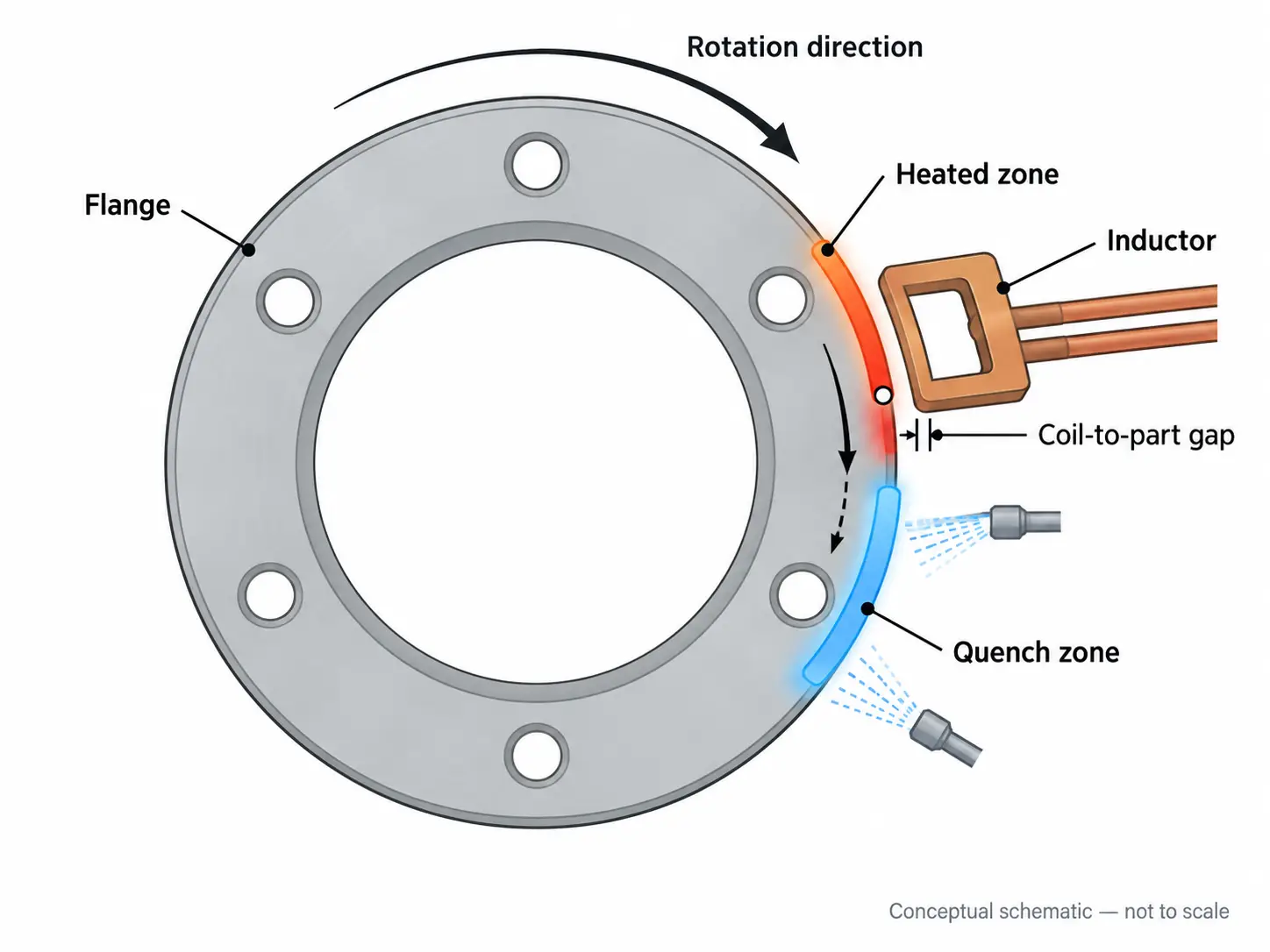
Rotating flange, localized inductor and spray quench position in circumferential hardening.
3. Coil Positioning, Gap and Radial Runout
The coil-to-part gap is the distance between the active induction coil and the workpiece surface. It affects electromagnetic coupling and the distribution of induced heating.
For large flange OD hardening, maintaining the intended coil-to-part relationship can be more difficult than on a smaller, accurately centered component.
How runout changes the coil gap
Radial runout causes the flange OD to move relative to its rotation axis.
If the workpiece rotates past a stationary inductor, this movement can produce a changing coil-to-part gap around the circumference.
A smaller gap generally increases electromagnetic coupling, while a larger gap reduces it. Depending on the coil design and operating conditions, these changes may alter the local heating rate or hardened pattern.
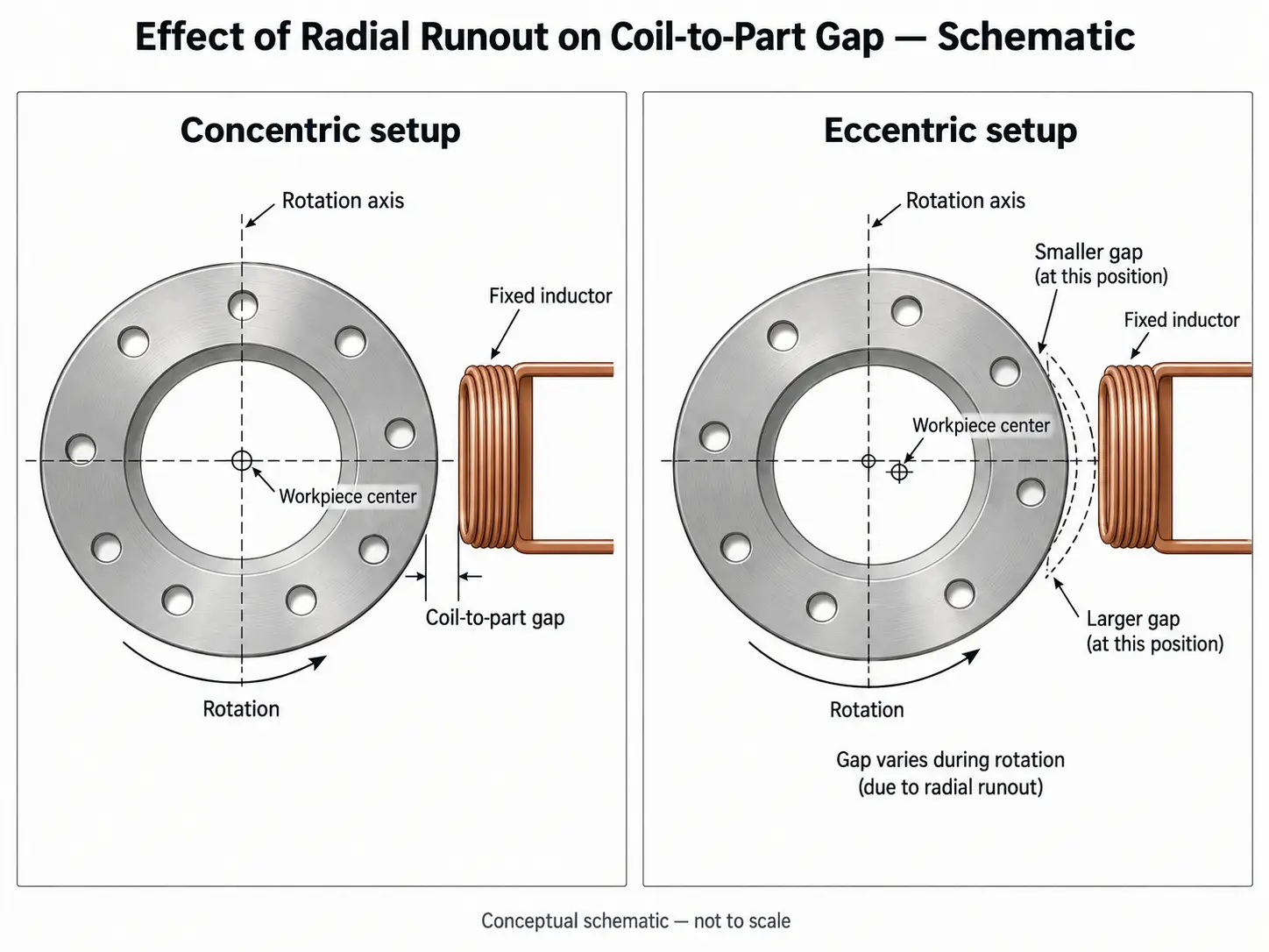
Radial runout changes the coil-to-part gap around the flange circumference.
This does not mean that every measurable variation in runout produces unacceptable hardness variation. The effect depends on the complete heating and quenching process.
ومع ذلك, when circumferential hardness or case-depth variation appears, radial runout and workpiece centering are reasonable conditions to examine before changing the power settings.
Coil alignment and flange geometry
The nominal gap is only one part of inductor positioning.
The coil must also align with the specified hardened band. If it is displaced axially or radially, the heated region may shift away from the required position.
Adjacent shoulders, steps and changes in section thickness can further affect heating distribution.
لهذا السبب, the inductor should be positioned relative to the actual flange geometry rather than the nominal outer diameter alone.
Important setup checks include:
— Workpiece centering and radial runout.
— Coil alignment with the required OD hardening band.
— Actual clearance throughout rotation.
— Fixture and support stability.
— Adequate clearance for dimensional variation and thermal movement.
The smallest possible coil gap is not necessarily the correct choice. The selected clearance must provide suitable coupling while accommodating the expected workpiece and machine movement.
Some systems may use controlled inductor positioning or gap tracking. A fixed inductor can also be appropriate when the mechanical arrangement maintains the required clearance.
4. Spray Quenching and Circumferential Hardening Continuity
Heating the flange to the required condition is only part of induction hardening. The subsequent cooling cycle determines whether the heated steel develops the intended hardened microstructure.
In a rotational arrangement, spray quenching must be coordinated with the heating zone and surface movement.
Spray position and quench timing
When the spray-quenching zone follows the induction coil, each surface location passes through heating before reaching effective cooling.
The time between these stages depends partly on the relative positions of the heating and quenching zones and the surface speed.
Changing RPM can therefore affect both heating exposure and quench timing.
A suitable spray arrangement also needs to cover the intended hardened band. Uneven spray distribution, blocked nozzles, changes in quenchant condition or incorrect spray positioning may contribute to differences in cooling.
A stable total flow reading does not necessarily demonstrate uniform local cooling at the workpiece surface.
The objective is not simply to maximize cooling intensity, but to establish cooling conditions appropriate for the steel and required hardened result.
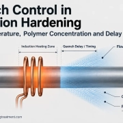
General quenchant characteristics, spray distribution and quench-delay control are discussed in التحكم في الإخماد في عملية تصلب الحث.
Why the start/end region deserves attention
A separate challenge can arise when a localized inductor scans around a complete circumference.
At the beginning and end of the hardening path, the material may experience a different thermal history from the intermediate region.
If the transition is not properly controlled, an insufficiently heated area may remain. بدلاً عن ذلك, overlap or local reheating may change the hardness of previously treated material.
Under certain conditions, this can produce a start/stop soft zone or discontinuity in the hardened layer.
This issue is associated with particular circumferential scanning methods. It is not an unavoidable defect in every rotating-workpiece process.
Specialized large-ring hardening systems use coordinated scanning arrangements to address this problem. على سبيل المثال, SAET Induction describes a multi-head seamless hardening system, بينما DKK describes a two-coil arrangement for controlling the joining region of large-ring scans.
These are specific large-ring applications, not universal equipment requirements for flange OD hardening.
Whether a flange needs complete circumferential hardening continuity depends on its engineering specification. Some components may permit a defined transition or untreated region.
Where a continuous hardened layer is required, the start/end region should be evaluated explicitly during process development and inspection.
5. How to Evaluate Hardening Uniformity
A stable machine program does not, في حد ذاته, prove that the specified hardened layer has been achieved.
For large flange OD hardening, the important question is whether hardness, case depth and hardened-pattern position meet the requirements at the relevant locations around the circumference.
Identify where the variation occurs
The location of an abnormal result can guide the initial investigation.
| Observed result | What to examine first |
|---|---|
| Hardness varies around the circumference | نفد, فجوة الملف, rotation and spray distribution |
| Soft region near the scan start/end | Heating overlap, transition sequence and quench timing |
| Hardened band is displaced | Coil alignment, workpiece positioning and treatment path |
| Surface hardness is acceptable but case depth varies | Heating exposure, coupling conditions and material response |
These observations help prioritize checks but do not establish a definitive cause.
على سبيل المثال, a local low-hardness region may be associated with insufficient heating, different cooling conditions or incoming material variation. Hardness measurements alone cannot reliably distinguish these possibilities.
Check more than surface hardness
Surface hardness and case depth describe different characteristics of the hardened layer.
A component can meet its surface hardness requirement at a measured point while having insufficient effective case depth or an incorrectly positioned hardened region elsewhere.
During process qualification, the inspection plan may therefore include hardness measurements at selected angular positions and cross-sectional examination of the hardened layer.
Particular attention should be given to locations where process conditions differ, including the start/end region when circumferential scanning is used.
Case-depth measurement methods and acceptance criteria should follow the applicable specification. ايزو 18203:2026 covers methods for determining the thickness of surface-hardened layers in steel, including those produced by induction hardening.
Dimensional checks may also be necessary where flange runout, roundness or other tolerances are critical.
Verify the cause before adjusting the process
If hardening variation is detected, first confirm the defect location and measurement results. Then compare those locations with the actual workpiece movement, coil position and quenching sequence.
Increasing power may not correct a problem caused by eccentric mounting. Changing rotation speed may alter both heating exposure and cooling timing. Adjusting the spray arrangement may affect the hardened result without correcting an underlying heating variation.
Any process adjustment should be verified against the actual hardening requirements.
For wider troubleshooting, انظر صلابة غير متساوية بعد التقسية بالحث.
الوجبات الجاهزة الرئيسية
Large flange OD induction hardening depends on three closely related conditions: how the workpiece moves through the heating zone, how the inductor couples with the surface, and how the heated region is quenched.
Reliable processing requires these conditions to be established for the actual flange geometry, material and hardening specification.
The final measure of success is not constant RPM, power or spray flow alone, but a verified hardened region that meets the required hardness, case depth and circumferential coverage.
الأسئلة المتداولة
انقر فوق سؤال لتوسيع الإجابة.
Why does constant RPM not guarantee uniform flange OD hardening?
At constant RPM, eccentric mounting or radial runout can move the outer diameter closer to and farther from a stationary inductor on each revolution, changing the coil-to-part gap and local heating. Rotation must be evaluated together with workpiece geometry stability, coil position and the quenching arrangement.
Does radial runout always cause hardness variation?
ليس بالضرورة. The effect of a changing coil gap depends on the complete heating and quenching process. ومع ذلك, when circumferential hardness or case-depth variation appears, runout and workpiece centering are reasonable conditions to check before changing power settings.
How is the start/end soft zone handled in circumferential scanning?
The beginning and end of the scan can experience a different thermal history, which may leave an underheated region or an overlap. Specialized systems use coordinated multi-head or multi-coil scanning to control the joining region. The start/end region should be evaluated explicitly during process development and inspection.
Why is surface hardness alone not enough to verify hardening uniformity?
Surface hardness and case depth describe different characteristics. A part can meet surface hardness at one point while having insufficient effective case depth or a misplaced hardened region elsewhere. Inspection should include hardness checks at selected angular positions and cross-sectional examination, with case-depth methods per the applicable specification.
Need to harden a large flange or ring outer diameter?
KOTRON supplies induction hardening equipment for flange, ring and disc outer diameter applications. مشاركة أبعاد الشغل الخاص بك, material and hardening specification to discuss a suitable process.