Camshaft Induction Hardening Machine
Vertical CNC Induction Hardening for Cam Lobes, Journals and Selected Camshaft Surfaces
Camshafts work under repeated contact, friction and cyclic loading. Their working surfaces need high wear resistance, while the core of the part must retain the toughness required during operation.
Induction hardening provides a way to heat and harden selected areas of a camshaft without treating the complete part in the same way. Cam lobe surfaces, journals and other specified working areas can be processed according to the part design and hardening requirement.
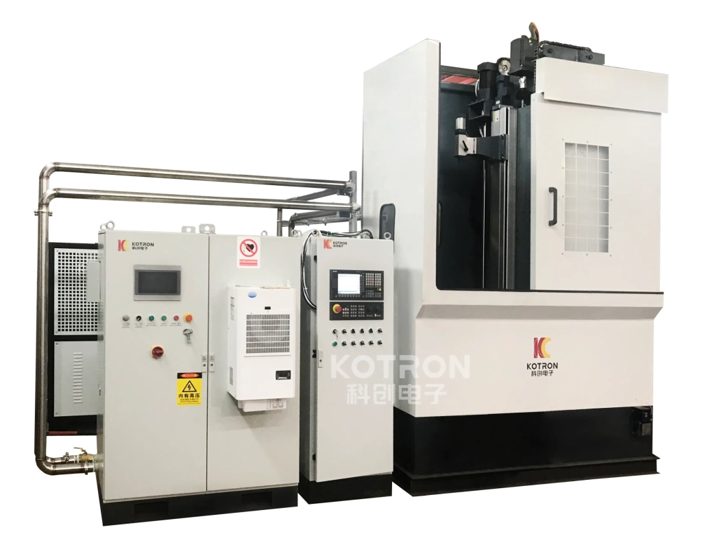
Our camshaft induction hardening system combines a vertical CNC hardening machine, DSP-controlled IGBT induction power supply, customized inductor and optional process monitoring system.
Ⅰ. Why Camshafts Need Selective Hardening
A camshaft is different from a conventional cylindrical shaft. Its geometry includes multiple cam lobes and journals, and the working surfaces are subjected to repeated contact and mechanical loading. The hardening process therefore needs to concentrate heat in the required areas while leaving other sections largely unaffected.
Induction hardening is well suited to this type of selective surface treatment. For camshaft applications, the process can be used to produce a hard, wear-resistant surface while retaining a tougher core. It can also improve resistance to cyclic loading in the hardened areas.
Depending on the part, selected cam lobe working surfaces, journals or other specified areas can be processed. This selective approach allows heat to be concentrated where wear resistance is required instead of heating the entire component uniformly. Cam lobes do not have the same cylindrical profile as a conventional round shaft, so the coil needs to be matched to the geometry and the intended heating area.
The hardening pattern is controlled through several related factors, including:
• Inductor geometry
• Operating frequency
• Output power
• Heating time
• Position of the heating zone
These parameters have to work together. Changing the workpiece geometry or hardening position may require a different coil or process setting.
Two camshafts can look similar while requiring different induction hardening conditions. Differences in cam lobe geometry, journal position, material and required hardened area can change the way the part couples with the induction field. This affects the inductor design as well as the required frequency, output power and heating time. For this reason, the camshaft itself remains the starting point for developing the heating process.
Ⅱ. KCJC-500H Vertical CNC Machine
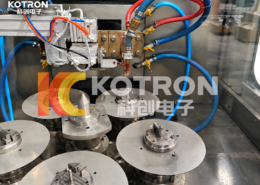
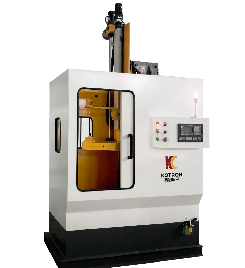
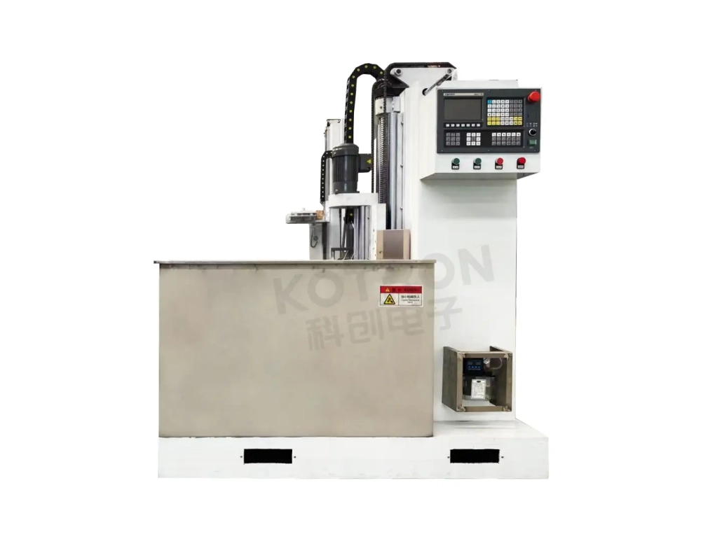
The recommended machine configuration is based on the KCJC-500H vertical CNC hardening machine. It is a vertical, single-axis, single-station machine suitable for induction hardening of shaft-type components, including camshaft applications. The vertical arrangement provides controlled workpiece clamping and rotation during the hardening cycle.
The KCJC-500H is equipped with a GSK96 CNC system. Workpiece rotation is driven by an asynchronous motor through a reducer, with spindle speed adjusted by frequency conversion. For workpieces of different lengths, the tailstock position can be adjusted according to the clamping requirement.
The machine can perform different quenching operations, including:
• Continuous immersion quenching
• Spray quenching
Its welded machine bed is stress-relief annealed to improve long-term dimensional stability.
Rotation is an important part of the hardening process. During operation, the machine holds and rotates the camshaft while the heating and quenching process is carried out according to the programmed sequence. The required movement depends on which surface is being treated. A cylindrical journal and a cam lobe do not present the same geometry to the induction coil, so the relationship between workpiece movement, inductor position, power and heating time needs to be established for the actual camshaft.
The CNC system provides the machine-side control required for repeatable movement and operation. This is particularly useful when the same camshaft is processed repeatedly in batch production.
Ⅲ. Customized Inductor for Camshaft Geometry
The induction coil determines where electromagnetic energy is concentrated on the workpiece. For camshaft hardening, the inductor should be developed around the shape of the camshaft and the required hardened area.
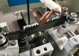
A customized profile coil can be used to match the cam lobe or other selected surface more closely than a general-purpose round coil. The purpose is not simply to put more heat into the part. Coil geometry, frequency, power and heating time all influence where and how the surface is heated.
Different camshaft designs may therefore require different inductors even when they are processed on the same type of machine.
Ⅳ. DSP IGBT Induction Power Supply
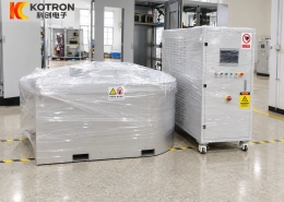
The heating system can be matched with the XZG series ultrasonic-frequency induction power supply. These power supplies use DSP full-digital control with IGBT transistor power conversion and a parallel resonant circuit.
Available control modes include:
• Constant current
• Constant power
• Constant temperature
The appropriate mode depends on the selected equipment configuration and heating process. Digital regulation allows the induction power supply to maintain controlled electrical output during the hardening cycle rather than relying only on fixed heating time. For camshaft production, this becomes particularly useful when different working areas or different part programs require separate process settings.
The following XZG power supplies are available as configurations for this type of induction hardening system.
| Model | Cabinet | Dimensions | Input Voltage | Input Current | Frequency | Output Power | Control Accuracy | Power Range |
|---|---|---|---|---|---|---|---|---|
| XZG-80SCZ | Single-door | 800 × 600 × 1750 mm | 380 V ±10%, 50/60 Hz | ≤170 A | 1–50 kHz | ≤80 kW | 1‰ | 5%–100% |
| XZG-100SCZ | Single-door | 800 × 600 × 1750 mm | 380 V ±10%, 50/60 Hz | ≤220 A | 1–50 kHz | ≤100 kW | 1‰ | 5%–100% |
| XZG-120SCZ | Single-door | 800 × 600 × 1750 mm | 380 V ±10%, 50/60 Hz | ≤250 A | 1–50 kHz | ≤120 kW | 1‰ | 5%–100% |
| XZG-160SCZ | Double-door | 1200 × 800 × 1750 mm | 380 V ±10%, 50/60 Hz | ≤350 A | 1–50 kHz | ≤160 kW | 1‰ | 5%–100% |
The specified power factor is ≥0.96.
These models are available configurations for camshaft and other shaft-type hardening applications. The table should not be read as meaning that every camshaft requires the same power or frequency. The actual heating setup depends on the workpiece and hardening process.
Ⅴ. Heating Control & Quenching
Induction power is only one part of the process. For a camshaft, the resulting hardened area is influenced by the combination of:
Inductor Geometry + Frequency + Power + Heating Time + Workpiece Position + Quenching
This relationship becomes more important when several cam lobes or journals have to be processed on one component. A process developed for one camshaft geometry cannot automatically be assumed to produce the same result on another part. The heating system and machine therefore need to operate as one process rather than as two independent pieces of equipment.
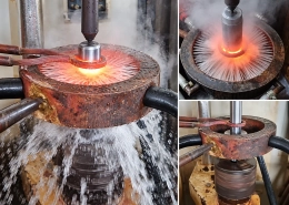
Heating has to be followed by controlled cooling to complete the hardening process. The KCJC-500H supports both spray quenching and continuous immersion quenching. The suitable quenching arrangement depends on the workpiece and process.
According to the material and hardening requirement, PAG quenching fluid or a suitable water-based quenching medium can be used. Quenching conditions influence the final hardening result just as heating conditions do, which is why the cooling stage should be considered together with the induction process.
Ⅵ. Process Monitoring & Traceability
For repeated production, checking only whether the machine completed the cycle provides limited information about what happened during heating. An optional hardening quality analysis and monitoring system can record and display process data throughout the induction hardening cycle.
Monitored parameters can include:
This gives the operator more information about the actual process rather than only the final machine status.
The monitoring system can compare the actual process curve with an established reference curve. Upper and lower process limits can also be defined. If the monitored process moves outside the specified limits, the system can generate underheating or overheating alarms.
Available functions include:
• Standard and actual curve comparison
• Upper and lower power-limit monitoring
• Underheating alarm
• Overheating alarm
• Historical process-data storage
• Workpiece parameter management
• Production data traceability
• Automatic identification of qualified and unqualified processing results
• Automatic pause and alarm for an identified non-conforming result
The workpiece database can store processing parameters for a large number of parts, making it possible to recall previously established production data when required. For recurring camshaft production, this provides a practical way to review whether individual heating cycles stayed within the defined process conditions.
The monitoring system provides the following display accuracy for the listed process parameters:
| Parameter | Display Accuracy |
|---|---|
| Current | 1 A |
| Voltage | 1 V |
| Frequency | 1 Hz |
| Energy | 1 KWS |
| Quenching Liquid Flow | 0.1 L/min |
| Cooling Water Flow | 0.1 L/min |
| Temperature | 0.1°C |
These values describe the monitoring-system display accuracy and should not be interpreted as the machining accuracy or hardening accuracy of the complete machine.
Ⅶ. Main System Configuration
A camshaft induction hardening system can be built around four main sections. These components work together around the camshaft hardening process instead of being selected as unrelated standalone units.
KCJC-500H Vertical CNC Hardening Machine
Provides workpiece clamping, rotation and controlled machine movement during the hardening process.
XZG Series DSP Induction Power Supply
Provides digitally controlled induction heating power, with available output configurations from 80 kW to 160 kW in the listed models.
Customized Induction Coil
Developed according to the camshaft geometry and the required hardened area.
Hardening Quality Analysis and Monitoring System
Monitors electrical and cooling parameters, records process data and provides alarm and traceability functions where this configuration is required.
Ⅷ. Typical Application
Camshafts are widely used as key components in automotive engines and are a typical application for induction surface hardening. The process is used where selected working surfaces require improved:
• Wear resistance
• Surface hardness
• Resistance to cyclic loading
At the same time, the core of the component retains the toughness required for mechanical service. The same induction hardening equipment platform can also be applied to other suitable shaft-type components, depending on their geometry and heat-treatment requirements.
Ⅸ. Frequently Asked Questions
Can the machine harden both cam lobes and journals?
Selected cam lobe surfaces, journals and other specified areas can be induction hardened according to the part and process requirement. The inductor and process settings need to match the area being treated.
Why does a camshaft need a customized induction coil?
Cam lobes do not have the same cylindrical profile as a conventional round shaft. Coil geometry therefore needs to be matched to the workpiece and intended heating area.
What induction power is available?
The listed XZG configurations include 80 kW, 100 kW, 120 kW and 160 kW models, with an operating frequency range of 1–50 kHz. These are available equipment configurations rather than fixed requirements for every camshaft.
What control modes are available for the induction power supply?
Constant-current, constant-power and constant-temperature control modes are available according to the selected system configuration.
Can the machine use spray quenching?
Yes. The KCJC-500H supports spray quenching as well as continuous immersion quenching.
Can the hardening process be monitored?
Yes. With the corresponding monitoring system, voltage, current, power, frequency, energy and cooling-related parameters can be displayed and recorded.
Can previous process data be reviewed?
The monitoring system supports historical data storage, workpiece parameter management and process traceability.
Can the system detect an abnormal heating cycle?
The monitoring configuration supports upper and lower process limits, curve comparison and underheating/overheating alarms. It can also identify non-conforming processing results and pause with an alarm.
Ⅹ. Camshaft Induction Hardening System
A camshaft hardening system is more than a vertical machine with an induction coil attached to it. The machine controls the workpiece. The induction power supply controls the heating energy. The customized inductor determines how that energy is coupled into the selected surface, while the quenching system completes the hardening cycle. Where process monitoring is required, electrical and cooling parameters can also be recorded and compared during production.
For cam lobes, journals and other selected camshaft surfaces, these parts of the system need to be considered together. The same vertical CNC platform can also be configured for other shaft-type components, such as the automatic gear induction hardening machine.
Camshaft Induction Hardening Machine
Vertical CNC Machine + DSP IGBT Power Supply + Customized Inductor + Process Monitoring