
Cam Lobe Induction Hardening: Prevent Cracking, Eliminate Defects & Select the Right Inductor
Cam lobe and shift fork induction hardening represents a distinct category within induction heat treatment — one where part geometry, fixture design, and inductor selection intersect in ways that directly determine process success or failure. Cam lobes demand single-shot precision with integrated quenching; shift forks force a choice between heating efficiency and zone control. This guide breaks down both processes, diagnoses the most common defects, and compares the two inductor approaches that define shift fork hardening practice.
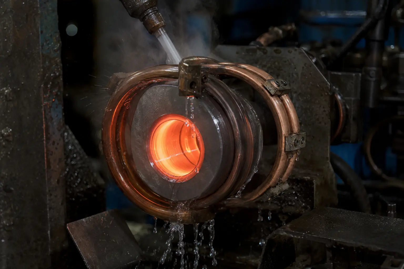
Table of Contents
1. What Is Induction Hardening of Cam Lobes and Shift Forks?
Cam lobes and shift forks are two functionally distinct automotive components that share a common requirement: localized surface hardening at precisely controlled case depths. Induction hardening is the dominant method for both, but the approach for each differs fundamentally.
Cam Lobes
Cam lobes — also called cam discs — are individual circular plates used in intake, exhaust, and oil pump cam applications. Material is typically GCr15 or 100Cr6 bearing steel. The standard hardening configuration is a ring-type single-shot inductor with integrated quench: the entire cam lobe periphery is heated and quenched in one cycle. Super-audio frequency (10–40 kHz) is used for most cam lobes; medium frequency (1–10 kHz) is reserved for heavy-duty types requiring deeper case depth.
Production equipment ranges from dual-station manual-loading machines to fully automated rotary-table lines — the choice driven by volume and cycle-time requirements.
Shift Forks
Shift fork materials include 45 steel, malleable cast iron, and alloy structural steels. The hardening requirement targets the fork face surfaces — the contact areas that engage the synchronizer sleeve. Surface hardness and case depth specifications vary by transmission design, typically calling for high-frequency or super-audio frequency equipment. Unlike cam lobes, the fork’s irregular geometry makes inductor design the central engineering challenge.
2. How Does the Induction Hardening Process Work?
Cam Lobe Process
The cam lobe hardening cycle is straightforward in principle but demanding in execution. The part is positioned concentrically within a ring-type copper inductor. When power is applied, the inductor’s magnetic field induces eddy currents around the entire outer circumference of the cam lobe, heating the surface to austenitizing temperature. Integrated quench sprays deliver coolant immediately after heating — all within a single-shot cycle lasting seconds.
This configuration produces uniform case depth around the cam periphery, provided the inductor is machined to tight concentricity and the part is correctly fixtured. The single-shot approach is inherently repeatable, which is why it dominates cam lobe production. Understanding induction heating frequency classification is essential for matching the power supply to the required case depth — super-audio for standard lobes, medium frequency when deeper hardening is specified.
Shift Fork Process
Shift fork hardening is less standardized than cam lobe work. The fork’s asymmetrical shape means the inductor must be designed specifically for each part number. Two distinct approaches exist — ring-style enclosure and outer-face heating — and the choice between them is the single most consequential decision in process development. We examine both in detail in Section 4.
The process fundamentals share much with other precision induction applications. Principles around induction heating power selection and coil efficiency apply directly — particularly the trade-off between heating speed and thermal conduction depth, which governs final case depth uniformity.
3. Common Defects and How to Prevent Them
The most frequently encountered problems in cam lobe hardening are cracking and edge chipping. These defects share a common root cause that is often overlooked during process troubleshooting.
The Burr Problem
Cracking and edge chipping are predominantly caused by burrs on the workpiece from prior machining operations. During induction heating, burrs act as stress concentrators — they heat faster than the surrounding material due to their higher surface-area-to-volume ratio, creating localized thermal stress gradients that initiate cracks at the part edge.
Solution: Adding a tumbling or vibratory finishing (vibratory deburring) step before induction hardening resolves this in the vast majority of cases. The step is inexpensive, easily integrated into the production line, and eliminates the root cause rather than compensating for it through process parameter adjustments.
What Is Not a Heat Treatment Problem
Two failure modes are frequently misattributed to induction hardening:
Cracking from grinding or press-fit: Post-hardening grinding with improper parameters (excessive feed rate, worn wheel, inadequate coolant) can generate grinding burns and cracks. Similarly, interference-fit assembly with excessive press force can initiate cracks at stress risers. Neither should be attributed to the hardening process without evidence. This principle extends to gear induction hardening defects as well — misattribution of grinding damage to heat treatment is a recurring problem across many part types.
Magnetic particle inspection indications within 0.3 mm: Linear indications of 0.3 mm or less found during MT inspection are generally forging laps — pre-existing material discontinuities from the forging process — and are unrelated to induction hardening. Distinguishing forging laps from quench cracks requires cross-sectional metallography.
4. Ring-Type vs Outer-Face Inductor: Comparing the Two Approaches for Shift Forks
Shift fork inductor design presents a genuine engineering trade-off with no universal answer. Two configurations dominate practice, each with distinct advantages and failure modes.
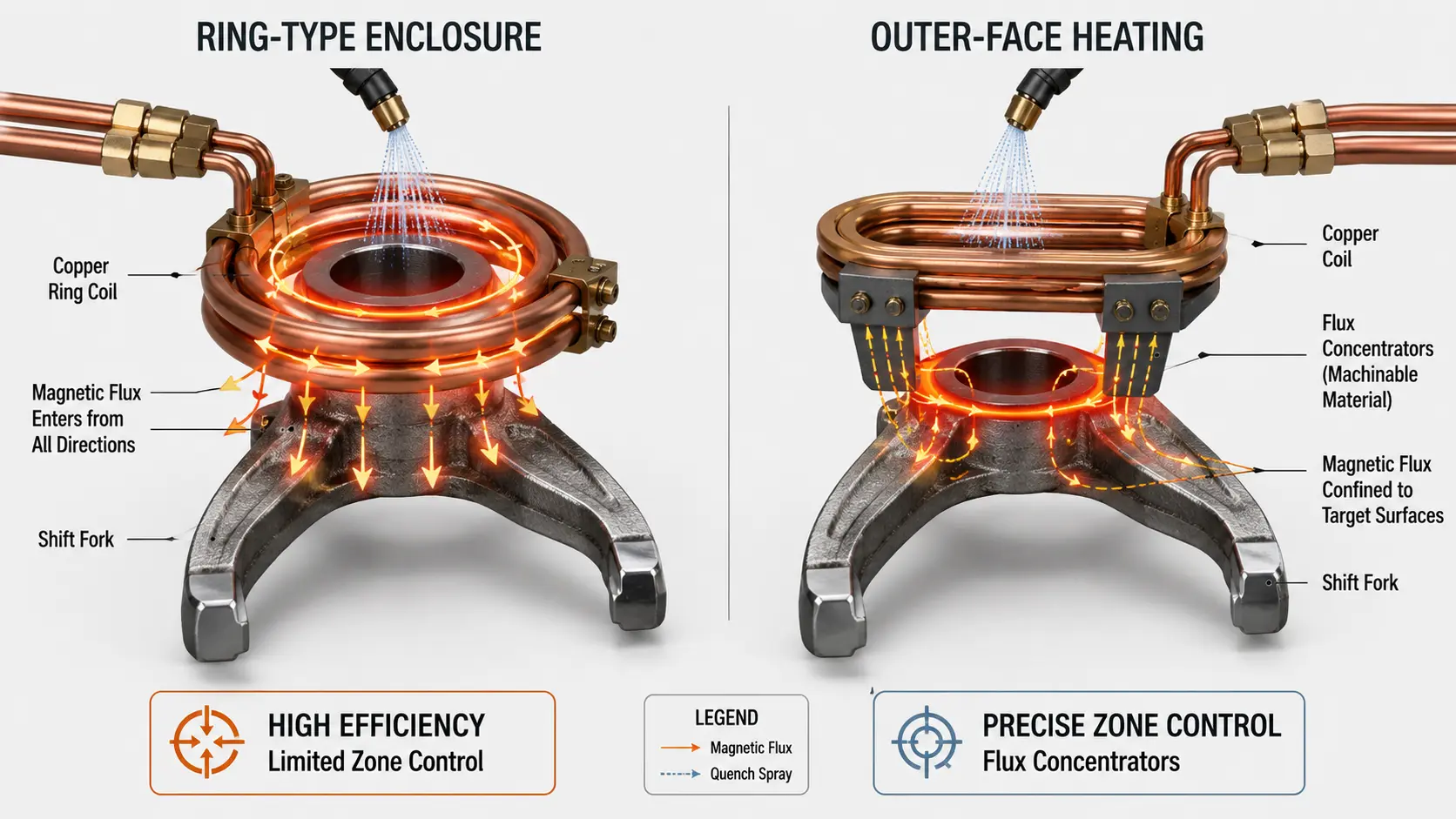
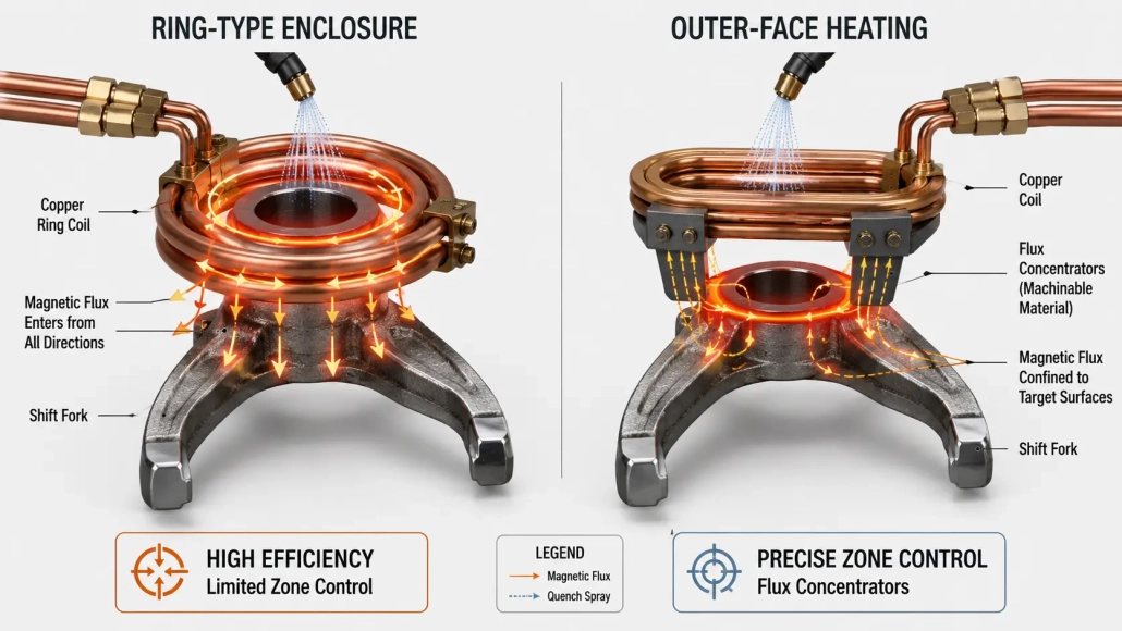
Approach A: Ring-Style Enclosure
A ring-shaped coil encloses the fork head, heating it from all sides in a configuration similar to the cam lobe approach.
Advantages: High heating efficiency — the enclosed geometry directs magnetic flux into the part from multiple directions, minimizing energy loss. Cycle times are short, and the inductor design is relatively simple to manufacture.
Disadvantages: Limited zone control. The enclosed coil heats the entire fork head, making it difficult to restrict the hardened zone to specific surfaces. The risk of through-hardening (hardening the entire cross-section rather than just the surface) or cracking is higher, particularly on thin-section forks.
Approach B: Outer-Face Heating with Flux Concentrators
Instead of enclosing the part, the coil uses its outer face to heat the fork surfaces. Flux concentrators are added to the inductor body to direct and confine the magnetic field to the target zones.
Advantages: Precise zone control — the hardened area can be limited to exactly the fork face surfaces that require it, leaving adjacent sections unaffected. This approach also allows multiple coils connected in series for simultaneous multi-point hardening, a significant productivity advantage in high-volume lines. The risk of through-hardening is virtually eliminated.
Disadvantages: Lower heating efficiency compared to the ring-style approach, requiring higher frequency to compensate. Inductor design is more complex, and flux concentrator material selection and machining add to tooling cost.
Which Approach to Choose?
The outer-face method with flux concentrators is the more commonly used approach in production, particularly for transmission shift forks where zone precision is non-negotiable. The ring-style approach is preferred when the fork geometry is simple enough that full-enclosure heating does not create over-hardening risks, and when cycle-time reduction is the primary objective.
The decision should be made during process development, not on the production floor. The cost of getting inductor design wrong — scrapped parts, field failures, or chronic process instability — far exceeds the cost of proper up-front engineering. For applications requiring precise case depth control, the principles discussed in our guide to shaft induction hardening challenges around frequency-to-depth mapping are directly applicable to shift fork processing.
🔑 Key Takeaway
Cam lobe induction hardening is a mature, standardized process: ring-type single-shot inductor with integrated quench, super-audio frequency, and a pre-hardening vibratory deburring step to eliminate the most common root cause of cracking.
Shift fork hardening is fundamentally an inductor design problem: the choice between ring-style enclosure (efficiency at the cost of zone control) and outer-face heating with flux concentrators (precision at the cost of complexity) must be made part-by-part, with zone precision typically winning out in production practice.
Need Help With Cam Lobe or Shift Fork Process Development?
Contact our engineering team for application-specific support on inductor design, defect troubleshooting, and process qualification for cam lobes, shift forks, and related automotive components.


