Piston Rod Induction Hardening Machine for Hydraulic Cylinders
Ⅰ. See the Piston Rod Induction Hardening Process
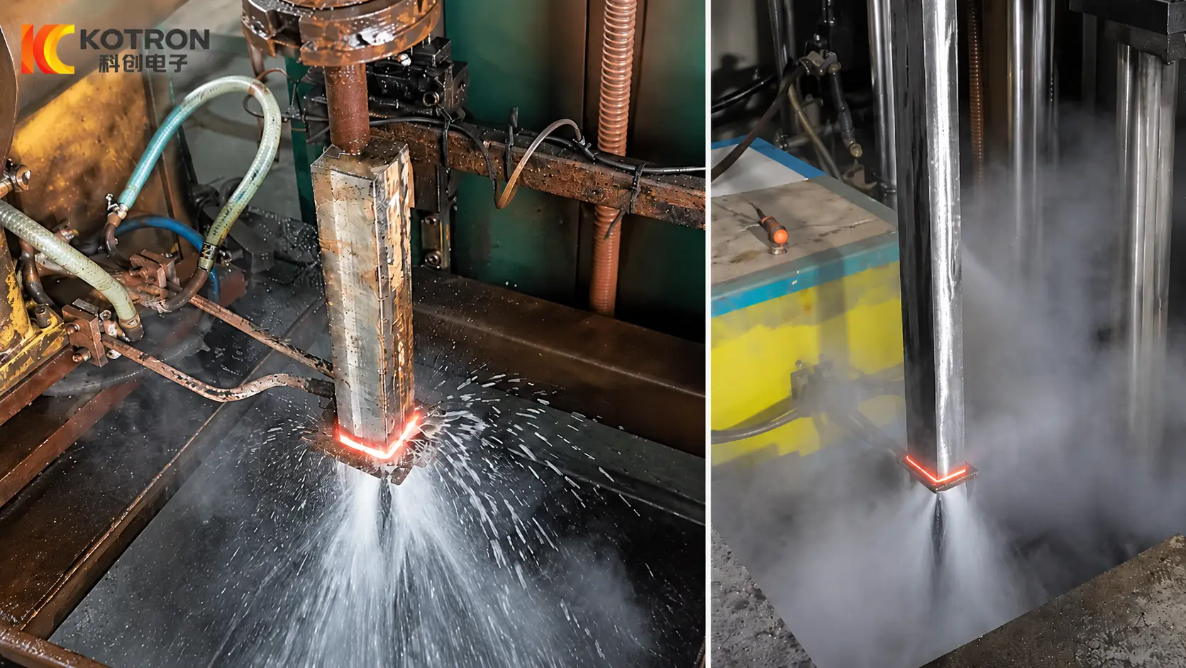
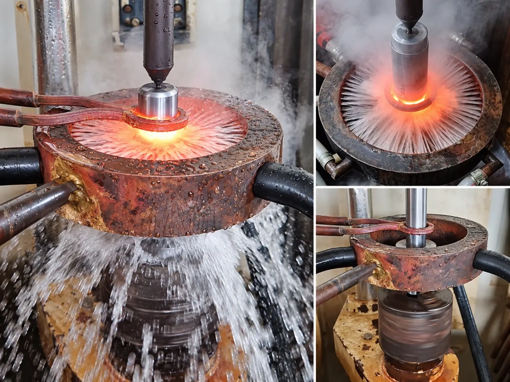
The video shows an actual piston rod during induction hardening.
The piston rod rotates while a localized surface area is induction heated and spray quenched. The heating is concentrated around the required surface region instead of heating the entire component at the same time.
Rotation can help reduce circumferential differences caused by variations in coil coupling, workpiece position and quench distribution. For cylindrical parts such as piston rods and shafts, this is useful when a consistent hardened surface is required around the circumference.
For a more detailed explanation of workpiece rotation during induction hardening, see: Why Does a Shaft Rotate During Induction Hardening?
The process shown in the video represents one actual project configuration. Different piston rod dimensions or hardening requirements may require a different inductor, movement method, rotation speed or quenching arrangement.
Ⅱ. Why Piston Rods Use Surface Hardening
Piston rods are long cylindrical components used in hydraulic cylinders and other reciprocating mechanisms.
During operation, the working surface can be exposed to repeated sliding contact, friction and mechanical loading. The surface condition therefore has an important influence on wear resistance and service performance.
Induction hardening makes it possible to heat a selected surface region and then quench it without treating the whole piston rod in the same way.
The objective is to obtain the required hardened surface while retaining suitable properties in the remaining section of the component.
There is no single hardness or case-depth value that applies to every piston rod. The correct process depends on the material grade, rod diameter, hardened length, drawing requirements and service conditions.
For this reason, the machine and hardening process should be selected from the actual piston rod specification rather than from a fixed standard parameter.
Ⅲ. How Piston Rod Induction Hardening Works
A piston rod hardening process has to coordinate the workpiece movement, induction heating and quenching system.
Rotation
The piston rod can rotate during the heating and quenching cycle. For a cylindrical component, rotation helps average small circumferential differences in coil-to-part spacing, electromagnetic coupling and spray distribution. The required rotation speed depends on the rod diameter, induction coil and hardening process.
Localized Induction Heating
The induction coil creates an electromagnetic field around the required area of the piston rod. Heat is generated directly in the workpiece, allowing a selected surface region to be heated without heating the entire component in the same way. The inductor is therefore designed according to the piston rod diameter, required heating width and target hardened area.
Scanning for Long Hardened Zones
When the required hardened area extends over a longer axial section, the machine can be configured for scanning hardening. Instead of heating the complete length simultaneously, a limited section is heated at one time while controlled relative movement takes place between the piston rod and induction assembly. Depending on the machine structure, either the workpiece or the induction assembly may provide the axial movement.
For more detail on these two machine arrangements, see: Why Some Induction Hardening Machines Move the Workpiece — While Others Move the Inductor
The suitable arrangement depends on workpiece length, weight, support requirements, machine structure and production method.
Spray Quenching
After the required surface region has been heated, quenching liquid is applied to cool the material rapidly and produce the required hardened layer. The relationship between the heating zone and the quenching zone is especially important in a scanning process. Depending on the inductor and machine design, the quenching system can be integrated close to the induction coil or arranged as a separate following spray system.
For more information about these two approaches, see: Induction Hardening Coil Design: Integral Quench or Separate Quench System?
The final hardening result depends on the combined effect of:
Frequency + Induction Power + Inductor Design + Rotation + Heating Time or Scan Speed + Quenching Conditions
These parameters should be developed as one process rather than adjusted independently.
Ⅳ. Machine and Inductor Configuration
A piston rod induction hardening machine combines workpiece handling, induction heating, process movement and quenching in one controlled system.
Depending on the project, the machine can include:
For long piston rods, machine stroke and workpiece support are particularly important. A short hydraulic cylinder rod and a long heavy-duty piston rod may require different support, clamping and travel arrangements even when they use the same basic induction hardening principle.
The induction coil is also designed for the actual workpiece. Coil diameter, effective heating width, coupling distance and quenching arrangement are selected according to the piston rod geometry and hardened-zone requirement. The inductor should therefore be considered part of the complete hardening process rather than simply a standard replaceable ring.
For other shafts, pins, rollers and more general shaft-hardening applications, see: CNC Shaft Induction Hardening Machine
This broader machine platform covers general shaft-type components, while this page focuses specifically on piston rods and hydraulic cylinder rods.
Ⅴ. IGBT Power Supply and DSP Digital Control
The induction power supply has to provide stable and controllable energy while the piston rod is being heated, rotated or scanned. Our induction heating systems use IGBT power conversion with DSP digital control. The IGBT inverter performs the high-speed power switching required by the induction heating circuit, while the DSP platform is used for control, monitoring and protection.
For a more detailed explanation of how the power system works, see: IGBT in Induction Heating Power Supplies: How It Works and Why It Is Used
Depending on the selected configuration, parameters such as current, voltage, power and operating frequency can be monitored during production. For recurring piston rod specifications, stored process programs can also help reproduce an established hardening process without resetting every parameter manually.
The induction power rating should not be selected from piston rod diameter alone. Rod material, diameter, required hardened depth, heating width, movement speed and production rate can all influence the required power and operating frequency.
Ⅵ. Customized for Your Piston Rod
A piston rod hardening system should be configured from the actual workpiece and process requirement rather than from one fixed machine model.
| Piston Rod Requirement | Machine / Process Configuration Affected |
|---|---|
| Rod diameter | Inductor size, frequency, power and support |
| Rod length | Machine stroke and support structure |
| Material grade | Heating and quenching parameters |
| Hardened length | Axial travel and process program |
| Required surface hardness | Heating and cooling process |
| Required case depth | Frequency, power density and heating conditions |
| End geometry | Fixture and coil clearance |
| Production rate | Power level and automation |
| Multiple rod sizes | Tooling, inductors and stored programs |
For example, two piston rods with the same diameter may still require different process settings if their materials, hardened lengths or case-depth requirements are different. Likewise, processing several piston rod sizes on one machine may require interchangeable induction coils, fixtures and stored process programs.
The final hardening result should be verified on the processed workpiece rather than judged only from machine settings.
For more information about hardness, hardened layer and inspection, see: How to Inspect Induction-Hardened Parts: Why Surface Hardness Alone Is Not Enough
Ⅶ. Additional Process Configuration
Process Control
CNC or PLC control can coordinate workpiece rotation, movement, induction heating and quenching according to the selected process program. For recurring piston rod specifications, established process recipes can be stored and reused.
Process Monitoring
Depending on the system configuration, operating parameters, alarms and production records can be monitored and stored for later review. For customers with higher traceability requirements, additional production and process-data recording can also be incorporated.
Cooling and Quenching
The quenching arrangement is selected according to the rod diameter, heating pattern and required hardened zone. Spray position and cooling capacity need to match the induction hardening process rather than being treated as an independent auxiliary system.
Automation
For batch piston rod production, the machine can be combined with automatic loading, unloading or workpiece transfer equipment according to production volume and factory layout. These functions are optional and should be selected according to the actual production requirement.
Ⅷ. Frequently Asked Questions
Click a question to expand the answer.
Can one machine harden different piston rod diameters?
Yes, provided the different workpieces remain within the mechanical and electrical working range of the machine. Different diameters may require different induction coils, fixtures, supports and process programs.
Does the piston rod rotate during induction hardening?
The actual process shown in our video uses workpiece rotation during induction heating and spray quenching. For other projects, the final rotation arrangement is selected according to the piston rod dimensions and hardening requirements.
Do all piston rods require scanning hardening?
No. Scanning is particularly useful when the required hardened area extends over a relatively long axial section of the piston rod. Short localized areas may use a different heating arrangement.
How is the hardened case depth controlled?
Case depth is influenced by several variables, including workpiece material, operating frequency, induction power, heating time or scan speed, coil design and quenching conditions. It should therefore be developed from the customer’s required effective case depth rather than from one universal machine setting.
Can the machine process several piston rod models?
Yes. Where several piston rod sizes are produced on the same system, different inductors, fixtures and stored process programs can be used. The practical working range depends on the machine stroke, clamping system, induction power and workpiece dimensions.
Can automatic loading and unloading be added?
Yes. For higher production volumes, loading manipulators, transfer mechanisms or unloading systems can be integrated according to the workpiece and production layout.
Request a Piston Rod Hardening Solution
To configure a piston rod induction hardening machine, please provide the basic workpiece and process information: Piston rod drawing + Diameter + Length + Material + Hardened area + Required hardness + Effective case depth + Production rate
Based on these requirements, we can evaluate the machine structure, travel, induction power, operating frequency, inductor design, rotation method and quenching arrangement for your project.