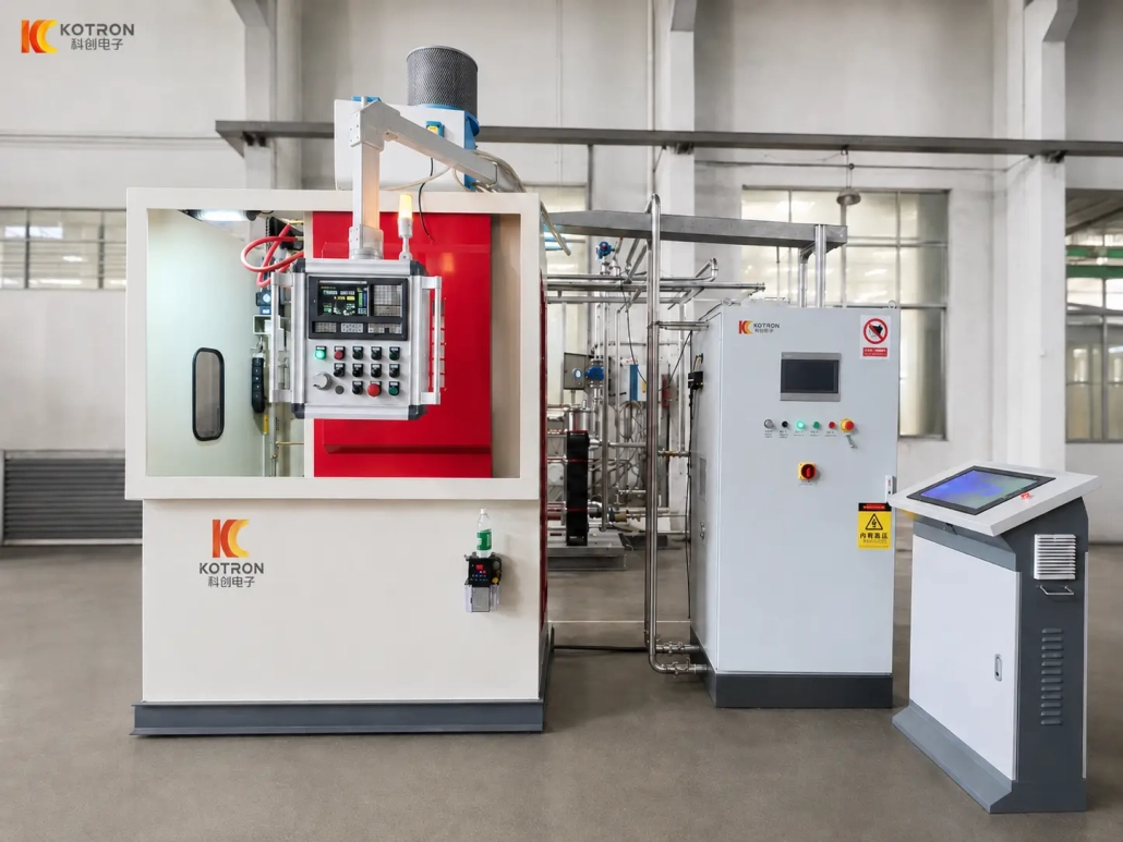
CNC Shaft Induction Hardening Machine
Ⅰ. Watch the Actual Hardening Process
Shaft OD Induction Hardening
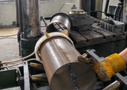
For the straight shaft shown in the video, the workpiece is positioned vertically inside a ring-type inductor.
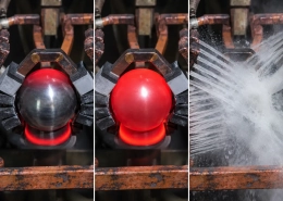
During the hardening cycle, the shaft rotates and moves upward through the heating zone. Rotation distributes the heating around the circumference, while the programmed vertical travel forms the hardened area along the shaft.
This type of scanning process is suitable for cylindrical shaft surfaces where a continuous hardened zone is required.
Internal Bore Induction Hardening
The same machine platform can also be configured for internal bore hardening by changing the inductor and corresponding tooling.
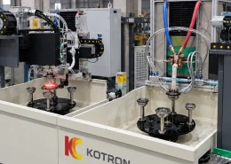
In the actual process shown here, a dedicated two-turn bore inductor is used around the internal hardening position, with the working assembly extending into the bore.
The inductor structure is selected according to the bore diameter, depth and required hardened area. A two-turn design is used for this particular application; other workpieces may require a different coil geometry.
Ⅱ. External Shaft and Internal Bore Hardening
One of the useful features of this machine platform is that the hardening process is not limited to a single surface.
For shaft outside-diameter hardening, a ring-type inductor surrounds the shaft. The workpiece rotates and travels vertically through the induction zone to produce a scanned hardened surface.
For internal bore hardening, the external inductor is replaced with a dedicated bore-hardening inductor. The inductor geometry and quenching arrangement are adapted to the internal surface.
This makes it possible to use the same CNC machine platform for different hardening positions without treating every part as a completely separate machine project.
The inductor itself is still workpiece-specific. Shaft diameter, bore size, hardening length, required case depth and available space around the part all affect the final design.
Ⅲ. How the CNC Hardening Machine Works
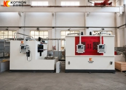
The vertical CNC machine controls the mechanical part of the hardening cycle.
The workpiece is first positioned and clamped between the corresponding locating and clamping components. Once the correct program is selected, the spindle rotates the workpiece and the feed system controls its vertical movement.
For the shaft process shown on this page, the sequence is:
The machine uses a servo motor and ball screw for the workpiece feed. The spindle rotation system provides variable-speed workpiece rotation. The KCJC-500H reference machine is specified as a vertical, single-axis, single-station machine with workpiece movement, a rotation range of 0–200 rpm and vertical repeat positioning accuracy of ±0.05 mm.
The GSK96 CNC system allows hardening programs for different parts to be selected, modified, stored and recalled. The available machine information also supports continuous hardening, spray hardening, piecewise scanning and fixed-position heating processes.
This allows an established movement sequence to be reused when the same part returns for another production batch.
Ⅳ. IGBT Power, DSP Digital Control and Centralized Operation
The mechanical movement of the machine and the electrical output of the induction power supply have different jobs in the hardening process.
IGBT Induction Heating Power Supply
Our induction heating power supplies use IGBT power conversion technology.
The IGBT power stage performs the high-speed electrical switching required to supply controlled medium- or high-frequency power to the inductor.
Power and operating frequency are selected according to the material, workpiece dimensions, heating position, required hardened layer and production cycle.
DSP Digital Control
The power supply uses DSP digital control to regulate the electrical output.
Available power-supply configurations support constant-current, constant-power and temperature-control modes, together with internal or remote control.
For the customer, the practical value is not simply the presence of an IGBT or DSP component. The important point is that induction power can be controlled as part of a repeatable hardening process and matched to different workpieces and recipes.
Central Control Console
The complete system also includes a separate central control console, which acts as the main operating point for the hardening system.
Together, the three sections form a complete equipment package:
— CNC machine — controls the workpiece movement
— IGBT induction power supply — provides the heating power
— Central control console — provides centralized system operation
Ⅴ. Customized Inductors and Tooling
The CNC machine provides the motion platform, but the final heating pattern depends heavily on the inductor.
There is no single universal coil for every shaft.
For an external cylindrical surface, the inductor normally surrounds the shaft. Coil diameter and heating width are selected around the shaft dimensions and required hardening zone.
An internal bore requires a different structure because the available space is smaller and the heating area is located inside the component.
Depending on the project, we can configure the machine with customized:
— External shaft inductors
— Internal bore inductors
— Workpiece fixtures and locating tooling
— Inductor positioning
— Quenching arrangements
The number of coil turns is also part of the inductor design. The bore process shown in the video uses a two-turn inductor, while the shaft process uses a different external coil configuration.
The correct solution is determined from the actual part rather than from the component name alone.
Ⅵ. Complete System Configuration
A shaft induction hardening project normally combines the mechanical machine, induction power supply and process-specific tooling rather than selecting only one machine model.
CNC Hardening Machine
The machine handles workpiece positioning, clamping, rotation and vertical movement. Its structure includes the machine bed, spindle system, feed drive and adjustable load platform. The KCJC-500H uses servo-driven ball-screw feed and a variable-speed workpiece rotation system.
IGBT Induction Heating Power Supply
Power is selected separately according to the part and process. The available company shaft-hardening information includes power-supply configurations from 40 kW to 250 kW across different shaft applications, rather than treating one power rating as suitable for every machine.
Central Control Console
The central console provides the operating interface for the complete equipment system.
Inductor and Tooling
These are configured around the workpiece geometry and hardening area. They may change even when the CNC machine platform remains the same.
Ⅶ. KCJC-500H Reference Machine Specifications
KCJC-500H is one available vertical CNC machine configuration for shaft hardening. The specifications below refer to the machine tool itself and should not be interpreted as the dimensional limits of every shaft-hardening system we can supply.
| Specification | KCJC-500H |
|---|---|
| Machine Type | Vertical CNC hardening machine |
| Station Configuration | Single axis, single station |
| CNC System | GSK96 |
| Workpiece Movement | Vertical |
| Operation | Manual / Automatic |
| Max. Workpiece Clamping Length | 500 mm |
| Max. Workpiece Diameter | 500 mm |
| Max. Hardening Length | 500 mm |
| Max. Workpiece Weight | 10 kg |
| Workpiece Rotation Speed | 0–200 rpm |
| Max. Running Speed | 0–100 mm/s |
| Vertical Repeat Positioning Accuracy | ±0.05 mm |
| Load Platform Adjustment | ±60 mm, front/rear and left/right |
Induction power and operating frequency are selected separately according to the workpiece and hardening process.
For longer, heavier or higher-throughput components, a different machine structure and power configuration may be required.
Ⅷ. Configure the Machine Around Your Workpiece
A shaft induction hardening machine should not be selected from shaft diameter or power rating alone.
A straight shaft requiring continuous OD hardening, a component requiring only a short localized hardened section, and a part requiring internal bore hardening place different demands on the machine, inductor and process.
For equipment selection, please provide:
• Workpiece drawing
• Material
• Overall dimensions
• Shaft or bore diameter
• Hardening area
• Required hardness
• Effective case depth
• Production rate
If several areas require hardening, mark them directly on the drawing.
Based on this information, we can evaluate the machine structure, induction power and frequency, inductor, tooling and hardening process together.
Frequently Asked Questions
Click a question to expand the answer.
Can the same machine handle both shaft OD and internal bore hardening?
Yes. The CNC machine platform is not limited to one surface. A ring-type inductor handles outside-diameter hardening; replacing it with a dedicated bore-hardening inductor switches the machine to internal bore work. The inductor and tooling are workpiece-specific, but the machine platform stays the same.
What size of workpiece can the KCJC-500H handle?
The KCJC-500H reference machine handles workpieces up to 500 mm in clamping length and 500 mm in diameter, with a maximum weight of 10 kg. These figures describe the machine tool itself, not the limit of every shaft-hardening system we supply.
How do I know which induction power supply to choose?
Power and operating frequency are selected separately from the machine, according to the material, workpiece dimensions, heating position, required hardened layer and production cycle. Shaft applications typically range from 40 kW to 250 kW; one power rating is not suitable for every part.
Is there a universal inductor for every shaft?
No. There is no single universal coil. External shaft inductors, internal bore inductors, fixtures, locating tooling and quenching arrangements are all configured around the actual workpiece geometry and hardening area.
What information do you need to configure a machine?
Send your workpiece drawing together with the material, overall dimensions, shaft or bore diameter, hardening area, required hardness, effective case depth and production rate. Mark each hardening area directly on the drawing.
Configure a CNC Shaft Hardening Machine Around Your Workpiece
Send your workpiece drawing and hardening requirements. We will evaluate the machine structure, induction power, frequency, inductor and tooling together.