
Induction Heating for Tool Steel: Practical Process Guidance
Table of Contents
- 1. Why Tool Steel Requires Careful Induction Heating
- 2. Where Induction Heating for Tool Steel Is Commonly Used
- 3. Selecting Frequency and Power for Tool Steel
- 4. Coil Design and Part Handling Considerations
- 5. Temperature Control, Soak Time, and Metallurgical Results
- 6. Common Process Risks and How to Reduce Them
- 7. When Induction Heating Is a Good Fit for Tool Steel
Induction heating for tool steel is a practical option when manufacturers need fast, controlled, localized heating for hardening, tempering, shrink fitting, brazing, or preheating high-alloy tooling components.
Tool steels are not forgiving materials. Their carbon content, alloying elements, carbide structure, and hardenability demand tight process control. A properly engineered induction system improves repeatability and cuts cycle time—but the power supply, frequency, coil, quench method, and temperature control must match the specific grade and production requirement. This article walks through the factors that matter, with concrete reference data for the most common tool steel grades.
1.Why Tool Steel Requires Careful Induction Heating
Tool steel is designed to resist wear, deformation, heat, and impact. These same properties make it more demanding to heat treat than low-carbon steel or simple alloy steel.
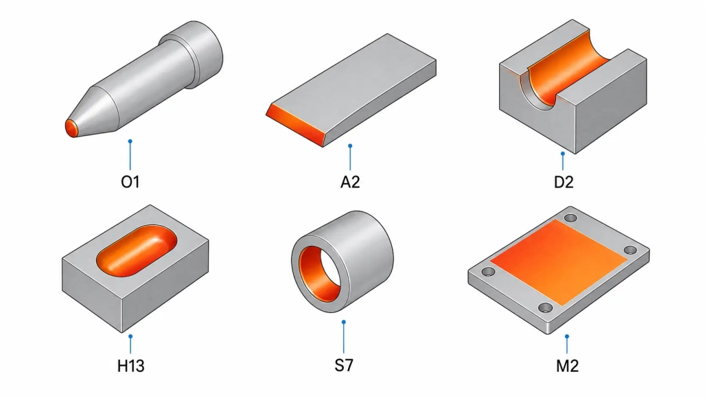
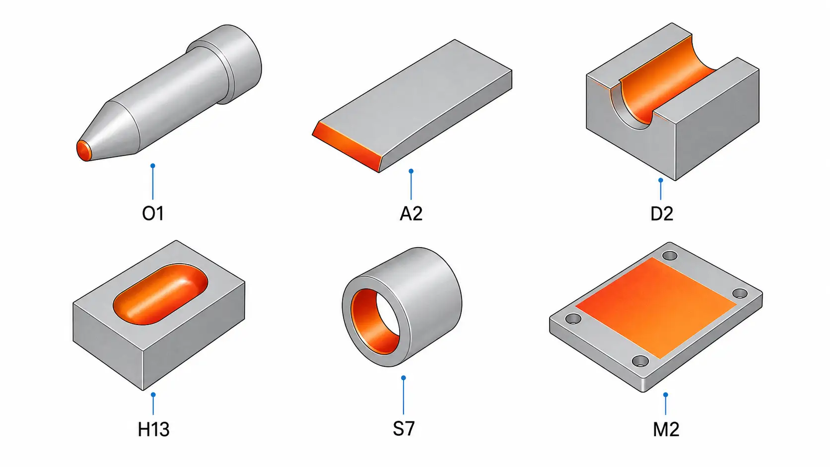
Grades such as O1, A2, D2, H13, M2, and S7 respond differently to heating and cooling. Some require tight austenitizing temperature control—H13 targets 1020–1050°C, D2 sits at 980–1020°C, and M2 demands an even narrower window around 1190–1230°C. Others are sensitive to cracking, retained austenite, decarburization, or distortion. The table below summarizes the key parameters for six common tool steel grades.
| Grade | Type | Austenitizing Temp | Quench | Typical HRC | Induction Notes |
|---|---|---|---|---|---|
| O1 | Oil-hardening cold work | 790–820°C | Oil | 60–64 | Narrow window; preheat to 200–300°C recommended |
| A2 | Air-hardening cold work | 925–980°C | Air | 58–62 | Air quench suits localized induction heating well |
| D2 | High-carbon high-chromium | 980–1020°C | Air / Oil | 58–62 | High carbide volume; uniform heating critical |
| H13 | Hot work | 1020–1050°C | Air / Oil | 46–52 | Two-stage preheat + triple temper required |
| M2 | High-speed steel | 1190–1230°C | Oil / Air | 62–66 | Extremely narrow austenitizing window; easy to overshoot |
| S7 | Shock-resisting | 925–955°C | Air / Oil | 54–58 | More forgiving; good candidate for induction hardening |
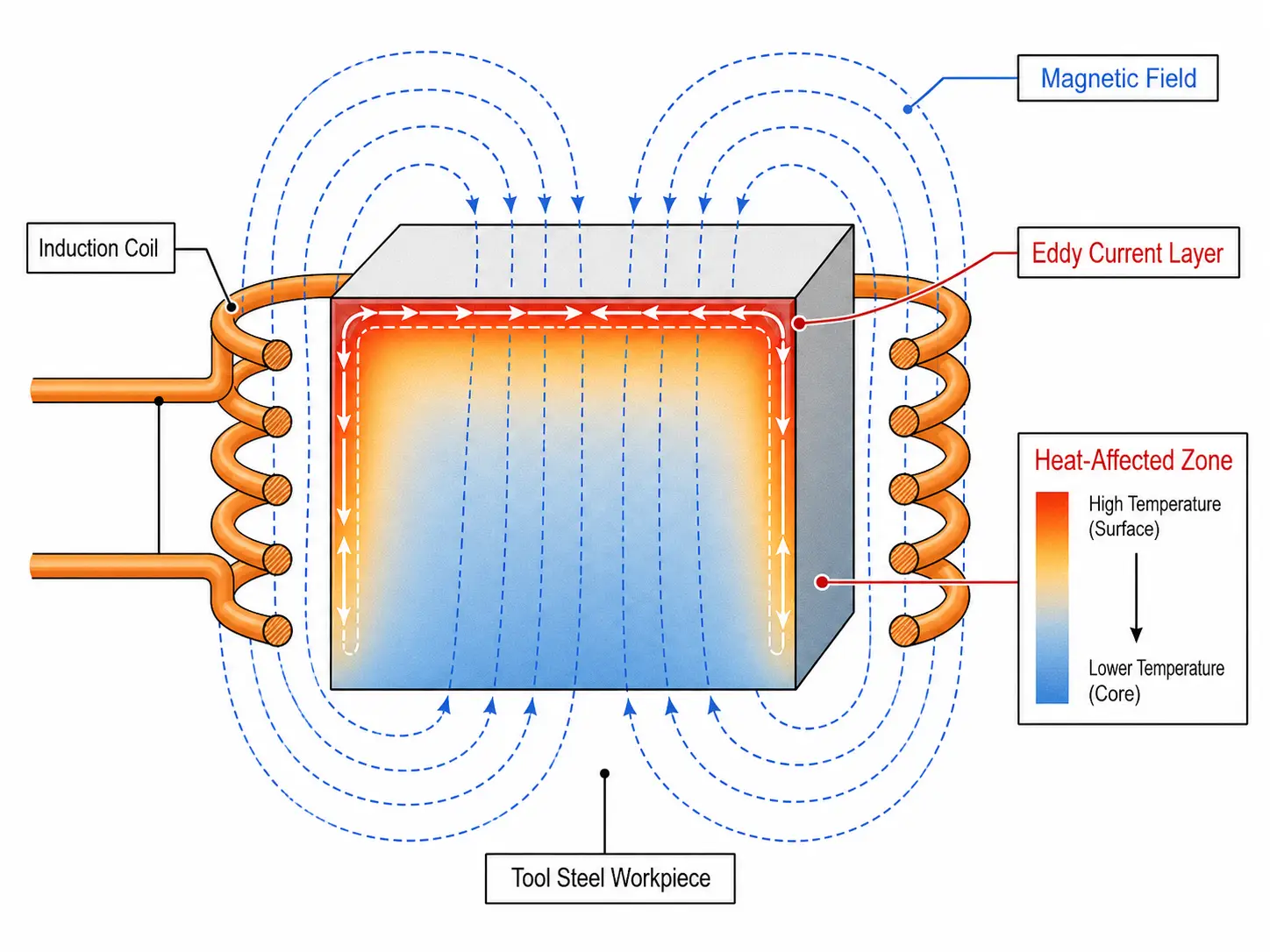
Induction heating delivers heat directly into the workpiece through electromagnetic energy—rapid, localized, and controllable. For many tool steel applications, that is a clear advantage over furnace heating when only a specific area needs treatment.
But induction does not eliminate metallurgical requirements. The process still demands the correct heating rate, target temperature, time at temperature, cooling method, and post-heat treatment. For fundamentals, see how induction heating works. For how high-alloy materials behave differently under induction, our guides on titanium alloys and superalloys cover parallel challenges.
2.Where Induction Heating for Tool Steel Is Commonly Used
Induction heating excels where the process benefits from fast, repeatable, localized heat—and where furnace heating is too slow or too imprecise. Common tool steel applications include:
- Localized hardening of cutting edges, punches, dies, and wear surfaces. Induction hardens only the working zone while the rest of the part remains tough. This reduces distortion and cycle time compared with heating the entire component in a furnace. See induction hardening and our guide on common hardening defects.
- Preheating before welding, brazing, or thermal repair. Rapid, uncontrolled heating creates steep thermal gradients and raises cracking risk in tool steel. Induction preheating delivers repeatable heat input with temperature feedback—useful for die repair, mold repair, and maintenance on high-value tooling.
- Brazing carbide inserts or wear pads to tool steel bodies. Induction concentrates heat at the joint area and limits overheating of the surrounding tool body. Joint design, filler metal, flux or atmosphere, and temperature control remain critical. See induction brazing for process details.
- Shrink fitting tool holders, sleeves, bushings, and precision assemblies. Rapid localized expansion with minimal distortion—a direct alternative to torch or oven heating.
- Tempering or draw-back operations on selected areas. When only a specific zone needs toughness adjustment, induction tempering avoids re-heating the entire part. See induction tempering machine selection for equipment guidance.
3.Selecting Frequency and Power for Tool Steel
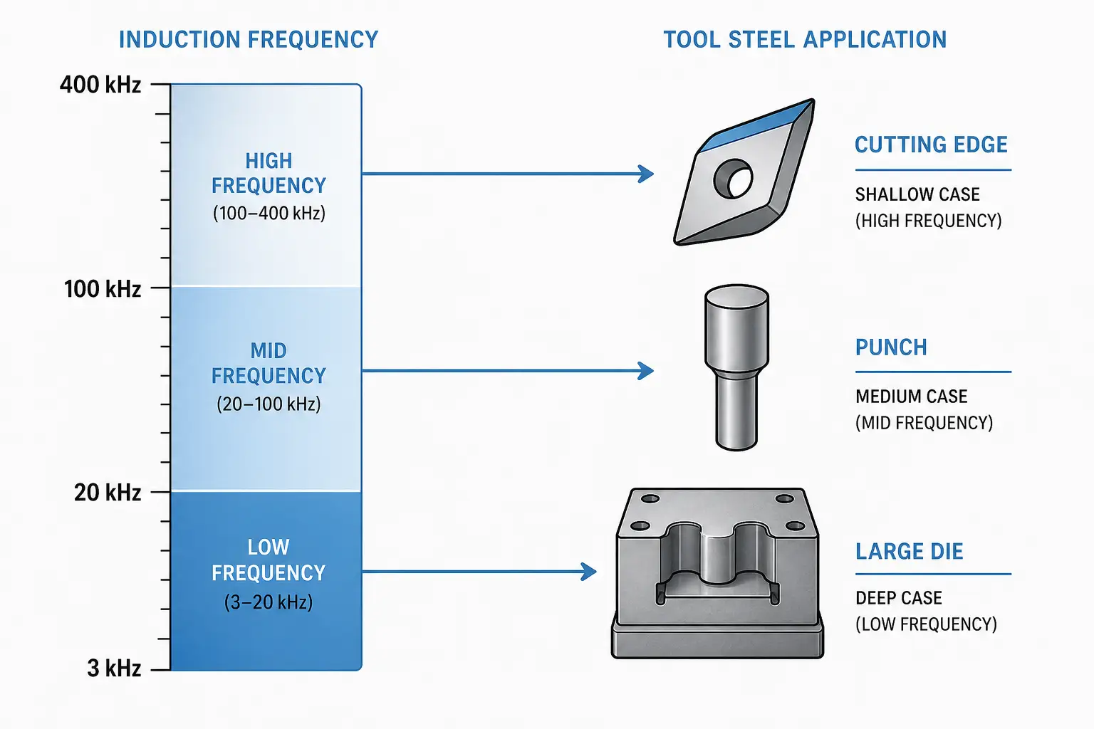
Frequency determines heating depth; power determines heating rate. The correct combination depends on part size, required case depth, geometry, grade, and cycle time.
Frequency selection
Higher frequencies heat closer to the surface; lower frequencies penetrate deeper. For tool steel, the reference ranges are:
| Case Depth | Frequency Range | Typical Tool Steel Application |
|---|---|---|
| Shallow (<1.5 mm) | 100–400 kHz | Cutting edges, shear blades, engraving tools |
| Medium (1.5–4 mm) | 30–100 kHz | Punches, forming dies, wear plates |
| Deep (>4 mm or large section) | 3–30 kHz | Large die blocks, mold bases, thick tool holders |
The goal is the correct metallurgical result at the correct depth without overheating edges, corners, or thin sections. Key factors: required heated depth, cross-section thickness, part diameter, geometry sharpness, coil-to-part coupling, and production rate. For more on the physics, see how frequency affects induction heating.
Power selection
Power must be high enough to reach temperature within the cycle time. Too much power density causes surface overheating, thermal shock, or non-uniform heating—especially at sharp corners and thin edges.
Heavy-section tool steel parts need significant power. Thin edges or sharp corners need reduced power density, coil optimization, rotation, scanning, or closed-loop temperature feedback. Power sizing depends on part geometry, material grade, target temperature, heating depth, duty cycle, and throughput. A trial run on actual parts is the most reliable way to confirm power supply sizing. See how much power for induction heating for calculation guidance.
4.Coil Design and Part Handling Considerations
The induction coil is one of the most critical parts of the system. A correctly sized power supply produces poor results if the coil does not match the part geometry and heating requirement.
Coil design controls heat pattern, coupling efficiency, repeatability, and process stability. Tool steel parts often have edges, holes, shoulders, keyways, slots, and varying section thicknesses that concentrate heat in unintended locations.
-
Coil geometry
A simple round coil works for cylindrical parts. Complex tool steel components need shaped coils, multi-turn coils, split coils, or single-turn inductors. For localized hardening, the coil must direct energy into the working surface while keeping adjacent areas cool. Flux concentrators help shape the magnetic field and improve efficiency on irregular geometries.
Key coil design factors: coil-to-part gap, number of turns, copper tube size and cooling, part rotation or scanning motion, heat pattern location, edge proximity effects, and quench access. For a deeper treatment, see how induction coils work.
-
Part positioning
Repeatable heating requires repeatable positioning. Small changes in coil-to-part gap shift heating rate and temperature distribution. For production, fixtures, rotation systems, servo slides, or robot loading maintain consistency when the process window is narrow.
Fixturing accounts for thermal expansion: tool steel moves during heating, and fixtures must avoid binding, marking, or creating cold spots.
-
Water cooling
Induction coils and power supply components need proper water cooling. Poor cooling shortens coil life and causes process drift. For sizing and maintenance guidance, see induction heating water cooling systems.
5.Temperature Control, Soak Time, and Metallurgical Results
Induction heating is fast, but tool steel metallurgy still depends on time and temperature. The required profile varies by grade, desired hardness, section size, and end-use conditions.
Many tool steels demand precise austenitizing temperature control. Too low, and the steel does not transform properly. Too high, and the result is grain growth, excessive retained austenite, carbide dissolution, or reduced toughness. The grade table in Section 1 provides target ranges for six common grades.
-
Heating rate and soak time
Induction brings a surface or localized area to temperature in seconds. For some applications—shallow case hardening of a cutting edge—that is the objective. For others requiring deeper penetration or uniform through-heating, the approach shifts: lower frequency, longer heat time, reduced power, scanning, rotation, or multi-stage heating.
Tool steels with significant alloy content need adequate time at temperature for carbide dissolution and transformation. When the application is critical, validate the process with hardness testing, microstructure review, case depth measurement, and dimensional checks.
-
Temperature measurement
Pyrometers, thermal cameras, thermocouples, and closed-loop power control serve different applications. Optical pyrometers are common for induction heating, but emissivity, surface condition, scale, oil, and geometry affect readings. In production, temperature measurement ties to a defined control strategy: power ramping, dwell time, part rotation, recipe control, and reject limits.
-
Quenching and tempering
Quench design matters as much as heating. Tool steels vary widely: O1 is oil-hardening, A2 and D2 are air-hardening, H13 needs controlled cooling. Induction systems use integrated spray quench, immersion quench, air blast, polymer quench, oil quench, or controlled cooling fixtures. The quench method must match the grade, heated depth, part geometry, and hardness requirement.
Tempering follows hardening to reduce brittleness and establish the final hardness-toughness balance. The practice follows the grade specification and end-use conditions. For equipment guidance, see induction tempering machine selection.
6.Common Process Risks and How to Reduce Them
Most tool steel induction heating issues trace to poor heat pattern control, excessive temperature, inadequate quenching, or inconsistent part presentation. The table below maps the four most common risks to their causes and prevention measures.
| Risk | Typical Causes | Prevention |
|---|---|---|
| Cracking | Sharp thermal gradients; excessive surface temperature; overly severe quench; sharp corners, keyways, or abrupt geometry changes | Preheat sensitive grades; control heating rate; match quench severity to the steel; temper promptly after hardening; radius sharp features where possible |
| Overheating / grain growth | Power too high; frequency mismatch; poor temperature feedback; insufficient soak time control | Closed-loop temperature control; correct frequency for depth; section and evaluate trial parts for critical applications |
| Non-uniform hardness | Inconsistent coil coupling; poor part rotation; uneven quenching; geometry-related heat concentration | Stable fixture and repeatable positioning; rotation for round parts; shaped coil or controlled scan path for complex geometry. See uneven heating troubleshooting |
| Distortion | Unbalanced thermal pattern; uneven quenching stress; inadequate fixturing during cooling | Dimensional inspection before and after heating; fixturing during heating or cooling for sensitive parts; localized heating limits distortion vs. full-furnace treatment |
When the part is expensive, safety-related, or used in severe service, section trial parts and evaluate microstructure before committing to production parameters.
7.When Induction Heating Is a Good Fit for Tool Steel
Induction heating is a strong fit when the requirement calls for localized heating, fast cycle time, repeatable heat patterns, or integration into an automated cell. It excels when only one area of a tool needs hardening or preheating—and when a furnace heats too much mass, creates excessive distortion, or slows production flow.
Induction is not the best option when the entire part requires uniform through-heating with extended soak time, when part geometry prevents effective coil access, or when production volume does not justify dedicated tooling. In those cases, furnace heat treatment remains more practical.
The best results come from treating induction as a complete process, not just a power supply purchase. Power supply sizing, frequency, coil design, quench design, controls, cooling, and fixturing all affect the final part. Define the required hardness, depth, temperature profile, quench method, and inspection criteria before selecting equipment.
FAQ
Q: What tool steels can be heated with induction?
A: Common grades including O1, A2, D2, H13, S7, M2, and related alloys. The correct process parameters depend on the grade—see the grade table in Section 1 for target temperatures and quench requirements.
Q: Is induction heating suitable for hardening tool steel?
A: Yes, especially for localized hardening. Validate the process with hardness testing, case depth measurement, and metallurgical inspection when the application is critical. See Section 2 for common applications.
Q: How do you choose frequency for tool steel induction heating?
A: Frequency depends on required heating depth and part geometry. Shallow case (<1.5 mm) typically uses 100–400 kHz; deep case (>4 mm) uses 3–30 kHz. See the frequency table in Section 3.
Q: Can induction heating reduce distortion in tool steel parts?
A: Yes—heating only the required area instead of the entire part reduces distortion. Results still depend on geometry, heating pattern, quench method, and fixturing. See Section 6 for distortion prevention measures.
Evaluate Your Tool Steel Heating Process
Share your tool steel grade, part drawing, target hardness, and production rate. Our engineering team can help review frequency, power, coil, and quench requirements for a practical induction heating solution.


