
How Induction Coils Work: Mastering 5 Critical Design Factors for Precision Heating Control
An induction heating power supply can deliver perfectly matched frequency and power — and the result can still be scrap if the coil is wrong. How induction coils work is not just about coiling copper tubing around a part. The coil is where electrical energy becomes magnetic field, and its geometry determines exactly where heat appears in the workpiece — and where it does not. A well-designed coil hits the target zone with minimal wasted energy. A poorly designed one misses the zone, overheats the wrong area, or burns through itself from inadequate cooling. This article explains what induction coils do, the common configurations, and the five design factors that separate a reliable coil from a process nightmare.
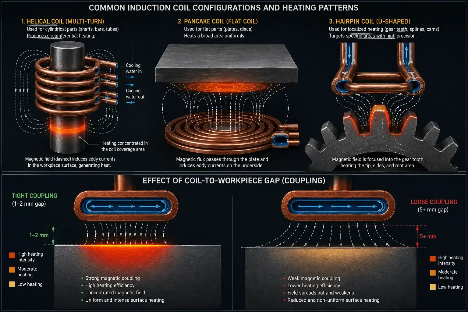
Table of Contents
1. What an Induction Coil Does
The induction coil — also called the inductor or work coil — is the component that converts electrical energy from the power supply into a magnetic field that interacts with the workpiece. It is typically made from copper tubing (high electrical conductivity) with internal channels for water cooling. The coil does not touch the part; it creates a magnetic field across an air gap, and that field induces eddy currents in the part surface. This is the same principle explained in our guide to how induction heating works — the coil is where that three-step process (current → field → eddy currents → heat) physically begins.
The coil’s job is deceptively simple: carry high-frequency alternating current and shape the resulting magnetic field so it concentrates in the target heating zone. Everything that matters — heating pattern, efficiency, cycle time consistency — traces back to how well the coil geometry matches the part geometry. A coil is not a generic component; it is application-specific tooling, like a cutting tool or a die.
2. Common Induction Coil Configurations
Induction coils come in several basic shapes, each suited to a particular class of part geometry. Custom coils often blend features from multiple types, but these four configurations cover the vast majority of industrial applications.
Helical (Solenoid) Coil
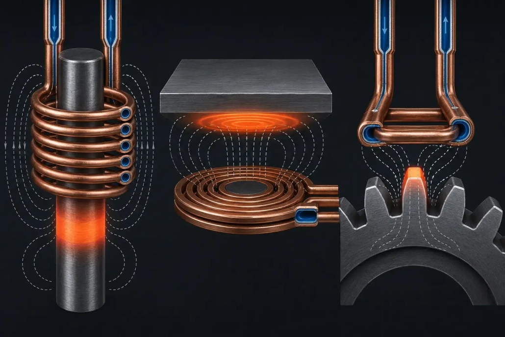
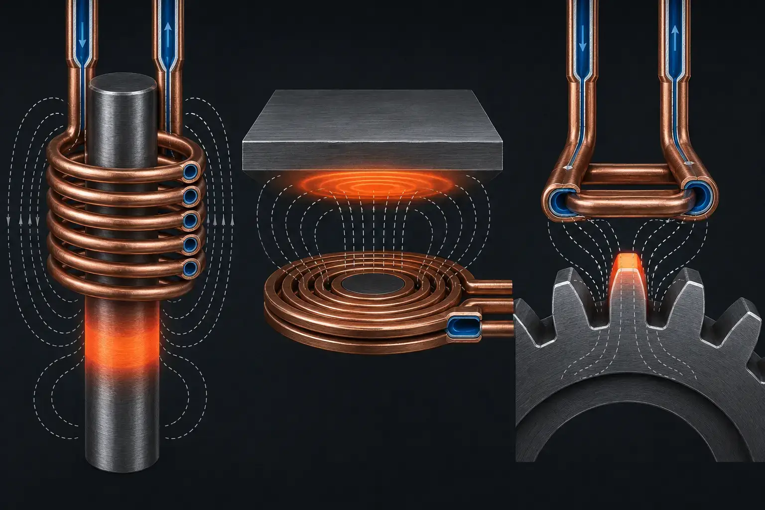
A helical coil wraps around the outside of a cylindrical part — shafts, pins, bearing rings, bar stock. The part sits inside the coil, so the magnetic field surrounds it uniformly. Helical coils produce consistent circumferential heating and are the workhorse configuration for OD (outer diameter) hardening of shafts and tubes. Multi-turn helical coils concentrate the field along the coil axis; single-turn versions produce a narrower, more tightly defined heat band. For shaft applications specifically, shaft induction hardening processes rely on this configuration, and coil-to-part concentricity is critical for uniform results.
Pancake (Flat Spiral) Coil
A pancake coil is wound flat — like a spiral on a single plane. It generates a magnetic field perpendicular to its face and is used for heating flat surfaces, end faces, or the underside of flanges. Pancake coils are also used in scanning applications where the coil moves across a large flat area. The heating pattern is a ring or disc that mirrors the coil winding, with the strongest field directly under the copper turns.
Hairpin (U-Shaped / Single-Loop) Coil
A hairpin coil is a U-shaped loop — essentially a single-turn inductor bent into two parallel legs. The magnetic field is concentrated between and around the legs, making it ideal for localized heating of specific features: a gear tooth, a cam lobe peak, a rail edge, or a small-diameter pin. This configuration is common in cam lobe and shift fork hardening where only a discrete contact surface needs treatment. Hairpin coils are often fitted with flux concentrators to steer the field precisely onto the target.
Internal Bore (ID) Coil
For heating the inside surface of a bore, ring, or tube, the coil must fit inside the part. ID coils are compact, often single or few turns, and cooling is especially demanding because the coil is surrounded by the hot workpiece with minimal space for heat dissipation. Our detailed guide to internal bore induction hardening covers the specific challenges of ID coil design, where magnetic concentrators on the inside of the coil are often essential to push the field outward toward the bore wall.
3. Five Design Factors That Control the Result
Coil design is a balance of competing requirements: tight coupling for efficiency versus enough clearance for the part to load and unload; high turn count for field strength versus manageable inductance; intense local heating versus avoiding coil burnout. These five factors drive every decision.
Factor 1: Coupling Distance (Magnetic Gap)
The distance between the coil surface and the workpiece surface — the coupling gap — is the single most influential coil design parameter. Magnetic field strength falls off rapidly with distance. A gap of 1–2 mm delivers strong coupling and high efficiency; a gap of 5 mm or more can drop efficiency by 30–50%. The practical lower limit is set by part loading clearance and the risk of arcing or mechanical contact during rotation. In production, coupling distance must be consistent part-to-part — variation in gap produces variation in heating, which produces variation in hardness.
Factor 2: Number of Turns
Adding turns increases the magnetic field strength for a given current — more amp-turns means more flux linking the workpiece. But more turns also increase the coil’s inductance, which shifts the resonant frequency of the tank circuit. The power supply must be able to match (tune to) the resulting load impedance. A coil with too many turns may push the resonant frequency below the supply’s operating range; too few turns may require more current than the supply or buswork can deliver. The turn count is a matching exercise between coil and power supply — not an independent choice.
Factor 3: Contour Matching
The coil should follow the part contour as closely as practical. If the part has a step, shoulder, or radius, the coil should mirror that feature to maintain uniform coupling distance across the heating zone. A cylindrical coil over a stepped shaft will heat the larger-diameter section more strongly (tighter coupling) and the smaller-diameter section weakly — producing an uneven pattern that cannot be corrected by frequency or power adjustments alone. For parts with complex geometry — gears with their tooth profiles or hub bearings with angular grooves — contour-matched coils are not optional; they are the difference between a passing and failing hardness pattern.
Factor 4: Internal Cooling Design
Induction coils carry hundreds or thousands of amps of high-frequency current. The copper itself has resistance, and that resistance generates heat inside the coil — independent of the workpiece heating. Without adequate water cooling, the coil can reach temperatures that anneal the copper (softening it), cause oxidation, or even melt through the tubing wall. Internal cooling channels must be sized for the expected current density, and water flow rates must maintain turbulent flow (not laminar) for effective heat extraction. On ID coils and other confined designs, cooling is the hardest constraint to satisfy.
Factor 5: Flux Concentrators
Flux concentrators — also called magnetic shunts or intensifiers — are inserts made from ferrite or laminated silicon steel placed around or inside the coil to redirect the magnetic field. They are not part of the electrical circuit; they are purely magnetic elements. A concentrator on the outside of a hairpin coil pushes the field inward toward the part rather than letting it spill uselessly into open air. On internal bore coils, a concentrator on the inside forces the field radially outward against the bore wall. Concentrators can transform a marginal coil into an effective one — but they add cost, complexity, and a failure point (ferrite can crack from thermal shock), so they are used where geometry demands them, not by default.
4. Matching Coil to Part Geometry
Coil selection starts with the part, not the power supply. Ask these questions in order: (1) What surface needs heat — OD, ID, face, or a discrete feature? (2) What is the target case depth — and therefore the required frequency for induction heating at that depth? (3) What clearance is available for loading — and therefore what coupling distance is achievable? (4) Does the part rotate during heating, or is it a static (single-shot) process?
The answer to these four questions narrows the coil configuration to one or two practical options. From there, turn count, tubing diameter, and cooling channel sizing are calculated to match the induction heating power supply output. The coil and the power supply form a resonant circuit — they must be electrically compatible or the system will not deliver rated power to the part. This interdependence is why induction heating frequency classification matters at the coil design stage, not just when selecting equipment.
For scanning (progressive) hardening, the coil is typically a single-turn or short multi-turn design that moves along the part, heating a narrow band that is immediately quenched. For single-shot hardening, the coil covers the entire heating zone at once — more complex to design, but faster cycle times for high-volume production. The choice between scanning and single-shot is a production economics decision that then drives the coil design.
🔑 Key Takeaway
The induction coil is not a generic accessory — it is application-specific tooling where electrical energy becomes magnetic field. Five factors determine whether the coil delivers: coupling distance (keep it tight and consistent), turn count (match it to the power supply), contour matching (follow the part geometry), internal cooling (size it for the current density), and flux concentrators (use them where geometry demands).
A coil that is mechanically right but electrically mismatched to the power supply will not deliver rated power. A coil that is electrically right but geometrically wrong will heat the wrong zone. Both must be correct — and they must be designed together, not independently.
FAQ
What is the best material for induction coils?
High-conductivity copper tubing is the standard material — specifically oxygen-free high-conductivity (OFHC) copper for demanding applications. Copper combines excellent electrical conductivity (minimizing coil heating from I²R losses) with good thermal conductivity (allowing effective water cooling). The tubing must have internal channels for coolant flow. For very high frequencies above 1 MHz, copper sheet or machined copper profiles are sometimes used instead of tubing because the skin effect confines current to an extremely thin surface layer.
How close should the coil be to the part?
As close as practical. A coupling gap of 1–3 mm is typical for precision hardening applications. Gaps below 1 mm risk arcing or mechanical contact; gaps above 5 mm lose significant efficiency. The gap must also be consistent around the entire heating zone — uneven coupling produces uneven heating. For rotating parts, the minimum gap must account for part runout and fixturing tolerance.
Why do induction coils need water cooling?
The copper coil carries very high current — often hundreds to thousands of amps — and copper’s electrical resistance, although low, generates significant I²R heating within the coil itself. Without active water cooling through internal channels, coil temperature rises rapidly, leading to copper annealing (softening), accelerated oxidation, and eventually coil failure. Cooling water must flow at a rate that maintains turbulent flow for effective heat extraction — laminar flow creates a boundary layer that insulates the copper from the coolant.
Need a Custom Induction Coil for Your Application?
Our engineering team designs application-specific coils — from simple helical inductors to complex contour-matched tooling with flux concentrators. Send your part drawing or description for a coil design recommendation.


