Dual-Station Automatic Induction Hardening for Motorcycle Engine Balance Shafts
Ⅰ. Motorcycle Engine Balance Shaft Application
A balance shaft is a rotating component used in motorcycle engines to help counteract engine vibration.
Depending on the engine design, a balance shaft may incorporate eccentric counterweights, stepped shaft sections, bearing journals and different diameter sections.
These geometric features make workpiece positioning, rotational stability and localized hardening important considerations during induction hardening.
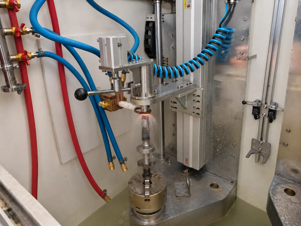
The equipment shown in this application is specifically configured for motorcycle engine balance shaft processing, using a vertical workholding arrangement and rotary scanning induction hardening.
The process focuses on the specified working sections of the balance shaft rather than heating the entire component uniformly.
Ⅱ. Automatic Dual-Station Design for Simultaneous Processing
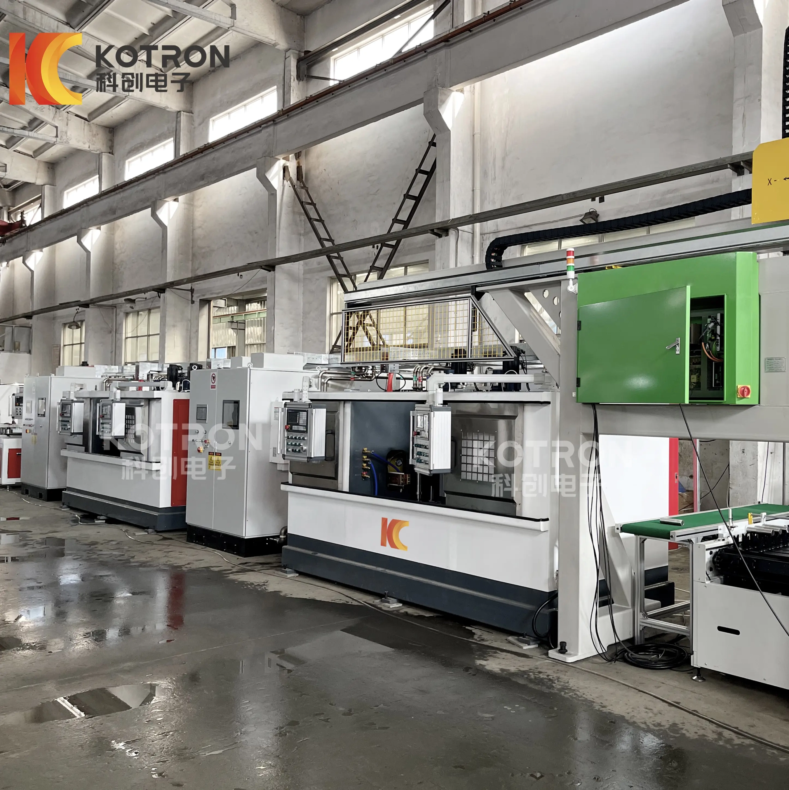
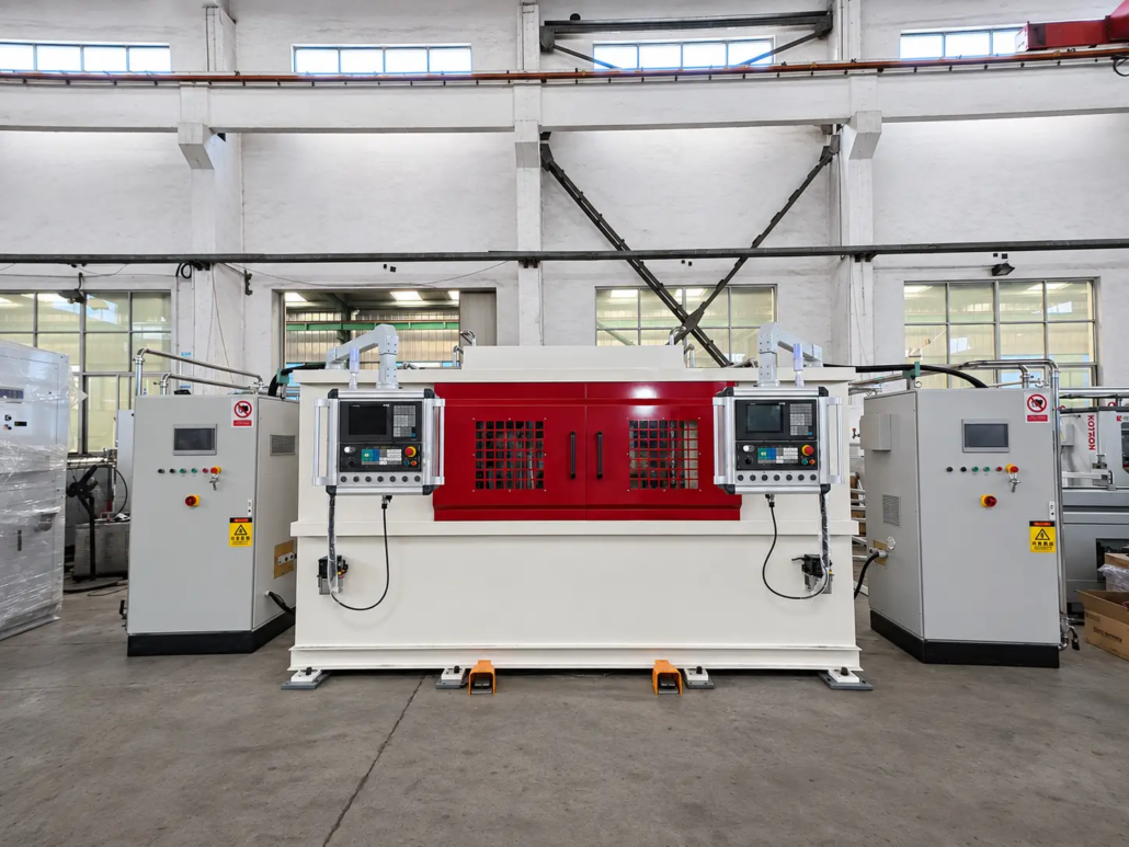
The machine integrates two working stations into one equipment structure.
Both stations can perform their induction hardening operations simultaneously, with each station equipped with its own dedicated induction coil.
This arrangement allows two workpieces to undergo their respective heating and quenching processes in parallel.
The dual-station configuration includes:
•Two simultaneously operating workstations
•Independent induction coil at each station
•Automatic workpiece clamping mechanisms
•Automatic positioning mechanisms
•Internal workpiece transfer mechanisms
•Vertical rotary workpiece movement
•Axial scanning movement
•Localized induction heating
•Spray quenching arrangements
•Machine operation and control interfaces
Compared with a single-station arrangement, simultaneous operation provides two processing positions within one machine and can improve production capacity when the heating cycles and workpiece requirements are suitable.
Actual production output depends on the workpiece, heating parameters, scanning distance, processing cycle and machine operating sequence.
Ⅲ. Automatic Workpiece Clamping, Positioning and Transfer
Automatic workpiece handling is an important part of this machine configuration.
The machine incorporates internal mechanisms for automatically clamping, positioning and transferring workpieces during the processing sequence.
These mechanisms coordinate workpiece handling with the two-station arrangement and the induction hardening operations.
The automatic handling functions include:
Automatic Clamping
The workpiece is secured by the machine’s clamping mechanism to maintain stable positioning during rotation and scanning.
Automatic Positioning
The positioning mechanism locates the workpiece in the required processing position before the induction hardening cycle.
Internal Workpiece Transfer
The machine incorporates a transfer mechanism to move workpieces within the equipment according to the programmed operating sequence.
These functions reduce the need for manual intervention in the internal workpiece handling process and help coordinate the mechanical movements with the induction heating cycle.
The external workpiece loading and unloading arrangement is determined by the actual production-line configuration.
Ⅳ. Vertical Rotary Scanning Induction Hardening Process
The machine combines workpiece rotation with axial scanning movement to achieve localized surface hardening.
After automatic clamping and positioning, the workpiece rotates while moving along its axial direction relative to the induction heating position.
This coordinated movement allows the selected shaft section to pass through the induction heating zone around its circumference.
The typical processing sequence includes:
①Workpiece Positioning. The workpiece is placed into the machine and positioned by the corresponding handling mechanism.
②Automatic Clamping. The internal clamping mechanism secures the workpiece in the required vertical position.
③Workpiece Rotation. The driving mechanism rotates the workpiece during the hardening process.
④Axial Scanning. The workpiece moves along its axis according to the programmed processing position and scanning distance.
⑤Induction Heating. The selected shaft section passes through the induction heating zone and reaches the required heating condition.
⑥Spray Quenching. Quenching liquid is applied to the heated area to achieve the specified surface hardening result.
⑦Internal Workpiece Transfer. The machine’s transfer mechanism moves the workpiece according to the programmed operating sequence.
Both stations are designed to perform their respective induction hardening operations simultaneously.
Ⅴ. Independent Induction Coils and Spray Quenching at Each Station
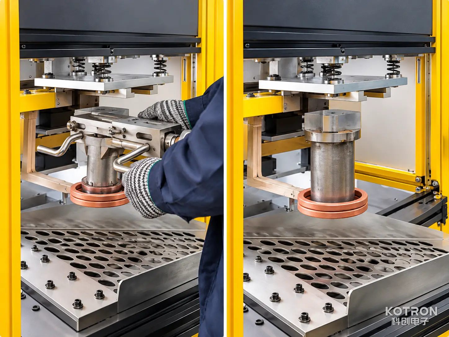
Each working station is equipped with its own dedicated induction coil.
This arrangement allows both stations to perform induction heating simultaneously without relying on a shared heating coil.
The coil geometry, heating clearance and position relative to the workpiece are important factors affecting the heating pattern.
During operation, the workpiece passes through the localized heating zone while rotating and moving axially.
A spray quenching arrangement is incorporated into the hardening process to cool the heated section after induction heating.
The heating and quenching conditions need to be matched to the material, workpiece geometry, required surface hardness and effective case depth.
The independent coil arrangement also allows the heating configuration at each station to be evaluated according to its corresponding workpiece and process requirements.
Ⅵ. Machine Structure and Control Configuration
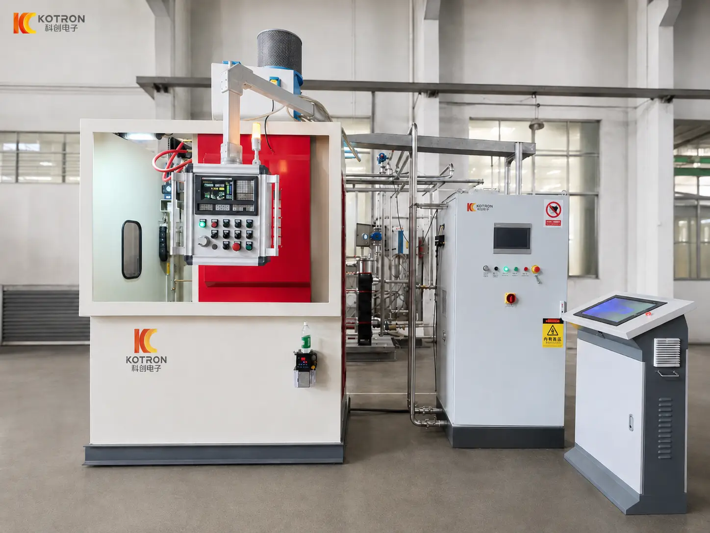
The complete machine integrates two working stations, automatic handling mechanisms and induction heating systems into one equipment structure.
The overall equipment layout includes two operator control panels positioned at the front of the machine, together with the corresponding electrical and auxiliary cabinets.
The control system coordinates the workpiece clamping, positioning, internal transfer, rotary movement, axial scanning and induction hardening sequence.
Important process and equipment configuration considerations include:
•Workpiece clamping and positioning
•Internal transfer sequence
•Station operating sequence
•Workpiece rotation
•Axial scanning distance
•Scanning speed
•Induction heating parameters
•Quenching sequence
•Equipment protection and operating status
The final electrical and control configuration should be selected according to the actual workpiece and production requirements.
Ⅶ. Processing Different Shaft Geometries
In addition to motorcycle engine balance shafts, the same equipment platform has also been shown processing another shaft component with a different external geometry.
Different shaft designs may have different:
•Overall lengths
•Shaft diameters
•Stepped sections
•Eccentric structures
•Clamping positions
•Required hardened areas
The corresponding fixture, induction coil and processing parameters should be evaluated according to each workpiece.
The automatic clamping, positioning and internal transfer mechanisms also need to be matched to the geometry and handling requirements of the selected component.
This demonstrates the equipment’s application to different shaft geometries without assuming that every component can use identical tooling or process settings.
Ⅷ. Technical Requirements for Equipment Selection
The correct induction hardening configuration cannot be selected from the workpiece diameter alone.
The material, component geometry, required hardened area and production requirements need to be evaluated together.
Workpiece Information
•Part name
•Material and grade
•Overall length
•Maximum and minimum diameter
•Workpiece weight
•Component drawing
Hardening Requirements
•Required hardening position
•Hardened area length
•Required surface hardness
•Effective hardened case depth
•Allowed deformation and dimensional tolerances
Production and Automation Requirements
•Required production output
•Simultaneous dual-station operation
•Workpiece clamping method
•Positioning requirements
•Internal transfer sequence
•External loading and unloading method
•Required processing cycle
•Production-line integration requirements
Based on these details, the machine structure, induction power supply, operating frequency, induction coils, workholding fixtures, handling mechanisms and quenching arrangements can be evaluated together.
Ⅸ. Frequently Asked Questions
Click a question to expand the answer.
Can both stations operate at the same time?
Yes. The machine is designed with two working stations that can perform their induction hardening operations simultaneously.
Does each station have its own induction coil?
Yes. Each working station is equipped with a dedicated induction coil, allowing both stations to perform their respective heating processes simultaneously.
Does the machine automatically clamp and position the workpieces?
Yes. The machine incorporates internal automatic mechanisms for workpiece clamping and positioning.
Does the machine include automatic workpiece transfer?
Yes. An internal transfer mechanism is integrated into the equipment to move workpieces during the processing sequence.
Does the machine have automatic external loading and unloading?
The machine has confirmed internal automatic clamping, positioning and transfer functions. The external loading and unloading arrangement depends on the actual production-line configuration.
How does the machine harden a motorcycle balance shaft?
The workpiece is positioned vertically and rotates while moving along its axial direction through the induction heating zone. The selected shaft section is heated and subsequently spray quenched.
Why does the workpiece rotate during induction hardening?
Rotation allows the induction heating process to cover the circumference of the selected shaft section rather than heating only one side of the workpiece.
What is the purpose of axial scanning movement?
Axial scanning allows the heating position to move along the shaft, making it possible to harden a specified section or length according to the programmed process.
Can the machine process other shaft components?
The equipment has also been shown processing another shaft component with a different geometry. The suitability of additional workpieces depends on their dimensions, fixture requirements and hardening specifications.
How is the required induction power selected?
Power selection depends on the workpiece material, dimensions, hardened area, required case depth, heating time and production cycle. A workpiece drawing and hardening specification are recommended for equipment evaluation.
Ⅹ. Request a Customized Balance Shaft Induction Hardening Solution
Motorcycle engine balance shafts have specific geometric and surface hardening requirements.
A suitable induction hardening system needs to coordinate automatic workpiece handling, vertical clamping, positioning, internal transfer, rotary scanning, localized induction heating and spray quenching.
This dual-station configuration provides two simultaneously operating working positions, each equipped with its own induction coil and automatic workpiece handling mechanisms.
To help us evaluate a suitable solution, please provide:
•Balance shaft drawing or sample photographs
•Workpiece material and grade
•Overall dimensions and weight
•Required hardened positions
•Surface hardness requirement
•Effective case depth
•Required production output
•External workpiece loading and unloading requirements
Based on these details, we can evaluate the dual-station machine arrangement, automatic handling mechanisms, induction power supply, operating frequency, induction coils, fixtures and hardening process.
Send Your Workpiece Drawing and Requirements
Provide the details above and we will evaluate the dual-station machine configuration, induction power supply, coils, fixtures and hardening process for your balance shaft.