
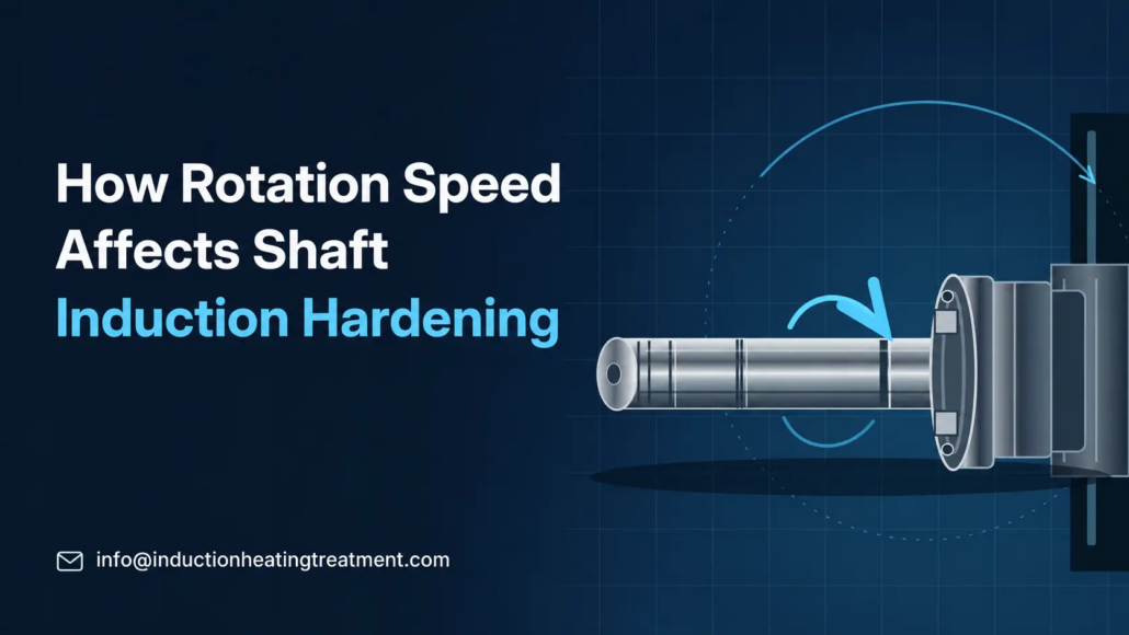
How Rotation Speed Affects Shaft Induction Hardening
How RPM, Inductor Design and Heating Time Influence Circumferential Uniformity
Rotation speed in shaft induction hardening affects how different positions around a workpiece’s circumference are exposed to induction heating and, in some processes, quenching.
Its importance depends on the inductor design. With an approximately symmetrical encircling coil, the heating field may already be relatively uniform around a cylindrical shaft. With certain single-shot inductors, rotation is essential for distributing uneven heating exposure around the circumference.
The correct RPM is therefore not simply the highest available machine speed. It must provide sufficient rotation during the relevant heating and quenching stages while maintaining stable workpiece positioning.
Understanding the relationship between RPM, heating time, inductor geometry and actual shaft movement helps engineers evaluate circumferential hardness differences and establish repeatable hardening conditions.
2. Why Does Inductor Design Change the Required Rotation Speed?
3. How Do RPM and Heating Time Determine Circumferential Exposure?
4. What Happens When Rotation Is Too Slow or Unstable?
5. How Does Shaft Rotation Affect Quenching Uniformity?
6. How to Troubleshoot Circumferential Hardness Differences
7. How Can the Correct Rotation Speed Be Verified?
1. Why Does Shaft Rotation Matter in Induction Hardening?
Induction heating generates heat within the workpiece through an alternating electromagnetic field. The resulting temperature distribution depends on the inductor geometry, electromagnetic coupling, heating time and workpiece shape.
If the electromagnetic field is not distributed equally around the shaft, different angular positions may receive different heating intensities.
Rotation changes the angular position of the workpiece relative to the inductor. As the shaft turns, its surface passes through different regions of the heating field. Sufficient rotation can help average these differences over the heating period.
For example, when one side of an inductor produces stronger heating than another, a stationary shaft may develop a circumferential temperature difference. Rotating the shaft can distribute the exposure more evenly, provided the workpiece completes enough rotation during heating.
However, rotation does not automatically eliminate temperature differences caused by shoulders, splines, changes in diameter, incorrect positioning or unsuitable inductor geometry.
Rotation speed and axial scan speed are different parameters.
•Rotation speed (RPM) describes how quickly the shaft turns around its own axis.
•Axial scan speed (mm/s) describes how quickly the heating zone moves along the shaft.
Axial scan speed primarily influences the heating exposure of successive sections along the workpiece. Rotation speed influences how angular positions are exposed during that heating interval.
The effect of axial movement on case depth is covered separately in How Scan Speed Affects Case Depth and Hardness in Induction Hardening.
2. Why Does Inductor Design Change the Required Rotation Speed?
The importance of rotation differs between encircling scan-hardening inductors and traditional profiled single-shot inductors.
Encircling Inductors in Scan Hardening
In conventional shaft scan hardening, an induction coil surrounds the shaft while the coil and workpiece move relative to each other along the axis.
For a cylindrical shaft with an approximately axisymmetric encircling inductor, the electromagnetic heating field can be relatively similar around the circumference.
Rotation can help average smaller differences caused by coil connections, local field variations or workpiece positioning. However, the heating arrangement does not necessarily depend on high rotational speed in the same way as a traditional channel-type single-shot inductor.
Real operating conditions are not perfectly symmetrical. The inductor connections, magnetic field concentrators, adjacent metallic structures and shaft geometry can all influence local heating.
Consequently, an encircling coil does not guarantee identical heating at every angular position.
Profiled Single-Shot Inductors
Traditional single-shot inductors for shafts may use longitudinal copper conductors connected by crossover sections.
Unlike a conventional encircling scan coil, these conductors do not create identical heating conditions at all angular positions.
As the shaft rotates, different surface positions pass through the heating regions generated by the longitudinal conductors and crossover sections.
For this type of inductor, sufficient rotation is critical to obtaining a reasonably uniform circumferential heating pattern.
In Equipment Selection for Induction Hardening: Single-Shot Hardening, Part 2, induction-heating specialist Dr. Valery Rudnev discusses numerical simulation of a shaft heated using a single-shot inductor.
The simulation showed that insufficient shaft rotation produced substantial circumferential temperature variation, while a suitable rotational condition improved temperature uniformity.
The comparison highlights an important distinction:
| Factor | Encircling Scan-Hardening Inductor | Traditional Single-Shot Inductor |
|---|---|---|
| Heating arrangement | Coil surrounds the shaft; axial relative movement typically creates the hardened length | Profiled conductors heat the selected shaft region during a heating cycle |
| Circumferential field | Can be approximately symmetrical | Often has significant angular variation |
| Main role of rotation | Helps average remaining circumferential differences | Essential for averaging the nonuniform heating exposure in traditional designs |
| Important speed relationship | RPM combined with local heating exposure | RPM combined with the single-shot heating duration |
| Main verification | Actual rotation, concentricity, hardened pattern and quenching | Actual rotation, revolutions during heating, positioning and hardened pattern |
These distinctions describe common inductor arrangements, not every possible design. Special-purpose inductors and alternative hardening methods may use different movement requirements.
3. How Do RPM and Heating Time Determine Circumferential Exposure?
RPM alone does not establish how many times a shaft turns while it is being heated.
The heating duration is equally important.
Calculating the Number of Revolutions
For a shaft rotating at a constant speed during a stationary heating cycle:
Number of revolutions = RPM × Heating time (seconds) ÷ 60
Consider a hypothetical four-second heating cycle.
| Rotation Speed | Heating Time | Revolutions During Heating |
|---|---|---|
| 60 RPM | 4 seconds | 4 revolutions |
| 120 RPM | 4 seconds | 8 revolutions |
| 180 RPM | 4 seconds | 12 revolutions |
At 60 RPM, the workpiece completes four revolutions during heating. At 180 RPM, it completes twelve revolutions over the same period.
Where the induction field varies substantially around the circumference, the number of revolutions can influence how evenly the heating exposure is distributed.
These values are calculation examples, not recommended settings for a particular shaft.
What Does Industry Literature Say About RPM?
In the single-shot hardening study cited above, Dr. Rudnev reports that rotation speeds for the discussed class of single-shot inductors commonly range from 120 to 500 RPM.
The article also discusses completing at least eight revolutions during the heating cycle, preferably more than twelve, depending on the workpiece size and specific inductor design.
These figures are useful reference points for understanding traditional single-shot hardening.
They are not universal requirements for shaft induction hardening.
A conventional encircling scan-hardening coil, a different single-shot design or a special-purpose hardening system may have different rotational requirements.
The appropriate speed also depends on heating duration, inductor geometry, mechanical stability and the required hardened pattern.
Calculating Revolutions During Scan Hardening
In scan hardening, using the complete machine cycle time can be misleading.
Each axial section of the shaft only passes through the effective induction heating zone for a limited interval.
As a simplified geometric approximation:
Local heating exposure time ≈ Effective heating-zone length ÷ Axial scan speed
The local number of revolutions can then be estimated as:
Local revolutions ≈ RPM × Local heating exposure time ÷ 60
For example, assume:
•Effective heating-zone length: 20 mm
•Axial scan speed: 5 mm/s
•Shaft rotation speed: 120 RPM
The estimated local heating exposure is:
20 ÷ 5 = 4 seconds
The corresponding rotation count is:
120 × 4 ÷ 60 = 8 revolutions
This illustrates why the full scanning cycle is not the correct interval for evaluating circumferential exposure at one axial position.
The calculation remains an approximation. The effective heating zone does not have a perfectly defined thermal boundary, and the actual temperature history depends on electromagnetic heating and heat conduction.
Most importantly, eight revolutions in this scanning example should not be interpreted as automatically meeting the rotation recommendation for a traditional single-shot inductor.
4. What Happens When Rotation Is Too Slow or Unstable?
Insufficient rotation and unstable rotation are related but different problems.
A shaft may rotate steadily at a speed that is unsuitable for its heating cycle. Alternatively, the selected RPM may be appropriate, but the workpiece may fail to follow the intended movement.
Insufficient Rotation During Heating
When an inductor produces an uneven circumferential heating field, too few revolutions during heating may leave different angular positions with different cumulative exposure.
Possible results include:
•Circumferential temperature differences
•Localized excessive heating
•Uneven austenitization
•Differences in effective hardened case depth
•Variation in the final hardness pattern
The effect is especially important with traditional single-shot inductors that rely on rotation to distribute heating around the workpiece.
With an approximately symmetrical encircling coil, the sensitivity to RPM may be lower, although actual operating conditions still need to be verified.
Workpiece Slippage
The programmed RPM does not always represent the actual shaft speed.
For example, where a drive mechanism transmits rotation through a clamping or contact arrangement, insufficient gripping force or wear may allow the driving mechanism to rotate without the workpiece following correctly.
Dr. Rudnev’s single-shot hardening discussion identifies worn workholding centers, slippage and excessive workpiece movement as possible causes of serious heating nonuniformity.
A motor-speed reading alone may therefore be insufficient.
When slippage is suspected, the actual rotation of the workpiece should be verified using an appropriate measurement method.
Runout and Eccentric Positioning
A shaft can maintain a constant rotational speed while its position relative to the coil changes during each revolution.
Excessive runout or eccentric positioning can cause the coil-to-part gap to vary.
This changes local electromagnetic coupling and can influence the resulting heating distribution.
Increasing RPM does not remove the underlying positioning error. In some setups, additional speed may also increase vibration or mechanical instability.
The correct response is to examine workholding, centering, shaft straightness and the actual coil clearance.
For a more detailed explanation of this relationship, see Coil-to-Part Gap in Induction Heating.
5. How Does Shaft Rotation Affect Quenching Uniformity?
The influence of shaft rotation does not necessarily end when induction power is switched off.
In some induction-hardening systems, the shaft continues rotating while quenchant is applied.
This can help distribute cooling exposure around the circumference when the spray arrangement is not perfectly symmetrical.
However, heating uniformity and quenching uniformity must be evaluated separately.
A shaft may receive sufficiently uniform heating but still develop an uneven hardened result because of differences in cooling.
Relevant quenching variables include:
•Spray distribution around the circumference
•Quenchant flow and pressure
•Nozzle or quench-ring condition
•Quenchant temperature and condition
•Timing between heating and cooling
•Actual shaft movement during quenching
Rotation changes how the moving surface interacts with the spray pattern. Too little angular movement may be unsuitable for arrangements that depend on rotation to average uneven coverage.
Increasing RPM is not automatically beneficial either. The chosen speed must be compatible with the spray geometry, effective cooling conditions and mechanical system.
For this reason, the heating and quenching stages may need to be evaluated together when establishing the operating program.
A low-hardness area on one side of a shaft does not, by itself, show whether the problem originated during heating or cooling.
For detailed information on cooling variables, see Quench Control in Induction Hardening.
6. How to Troubleshoot Circumferential Hardness Differences
When hardness or case depth varies around a shaft, changing RPM should not be the first automatic response.
The observed pattern should be compared with actual rotation, inductor geometry, workpiece positioning and quenching conditions.
The following table identifies useful starting points for investigation.
| Observed Problem | What to Check First |
|---|---|
| One side of the shaft has lower hardness | Actual rotation, coil-to-part gap, eccentricity and quench distribution |
| Motor RPM is stable, but the workpiece moves inconsistently | Drive transmission, clamping, slippage and actual shaft rotation |
| A traditional single-shot inductor produces uneven circumferential heating | Revolutions during heating, inductor geometry and workpiece positioning |
| Increasing RPM does not improve the hardened pattern | Coil design, runout, actual heating conditions and spray coverage |
| Surface hardness is acceptable, but case depth varies around the circumference | Local heating exposure, temperature distribution and circumferential hardness-depth profiles |
| Results change between production batches | Workholding condition, actual RPM, inductor position, quench delivery and process-record differences |
These observations are investigation priorities, not definitive diagnoses.
For example, a softer area on one side of the shaft can result from insufficient local austenitization, inadequate cooling or a combination of conditions.
Similarly, an uneven case-depth pattern does not prove that rotation speed was incorrect.
A broader discussion of possible hardening defects is available in Uneven Hardness After Induction Hardening.
The purpose of an RPM investigation is to establish whether actual rotational exposure contributed to the observed variation, rather than assuming every circumferential defect is a speed problem.
7. How Can the Correct Rotation Speed Be Verified?
A suitable RPM should be established through actual machine behavior and finished-part inspection.
The selected speed must be appropriate for the heating arrangement, mechanically repeatable and capable of contributing to the required hardening result.
① Confirm Actual Workpiece Rotation
Where RPM materially affects heating uniformity, check whether the shaft itself follows the commanded rotation.
Depending on the equipment, verification may involve actual workpiece speed measurement, position feedback or another suitable monitoring arrangement.
Checking only the drive motor may not reveal slippage between the drive and workpiece.
② Check Rotation During the Relevant Heating Interval
For traditional single-shot hardening, compare actual RPM with the heating-cycle duration and calculate the number of completed revolutions.
For scan hardening, consider the revolutions completed while each axial section passes through the effective heating zone.
Where acceleration, deceleration or speed variation occurs, a constant-RPM calculation may not represent the actual movement.
③ Check Positioning and Coil Clearance
Measure or otherwise evaluate:
•Workpiece centering
•Runout during rotation
•Fixture and center condition
•Coil-to-part clearance
•Vibration or unstable workpiece movement
These conditions should be assessed before attributing heating nonuniformity to rotational speed alone.
④ Evaluate the Finished Hardened Region
If circumferential uniformity is in question, measurements from only one angular position may be insufficient.
Where appropriate, compare hardness at defined positions around the same axial section.
For critical applications, prepared cross-sections and hardness-depth measurements at selected angular positions can provide more information about effective case depth and the hardened pattern.
The inspection method, measurement locations and acceptance criteria should follow the component specification.
⑤ Compare Controlled Process Trials
When evaluating an RPM adjustment, keep other relevant conditions comparable wherever practical.
These may include:
•Workpiece material and incoming condition
•Induction power and frequency
•Inductor design and position
•Heating time or axial scan speed
•Quenching arrangement and conditions
If several variables are changed simultaneously, the resulting difference cannot confidently be attributed to RPM.
After an appropriate rotational condition is established, the complete hardened result should be verified against the specification.
For detailed inspection methods, see How to Inspect Induction-Hardened Parts.
Rotation Control in CNC Shaft Hardening Equipment
In production equipment, rotation must operate together with the workholding, scanning and quenching mechanisms.
A CNC Shaft Induction Hardening Machine can provide programmable workpiece movement as part of an integrated induction-hardening process.
However, machine specifications alone do not establish the correct RPM for a particular component.
The selected movement program should be developed around the shaft geometry, inductor configuration, heating cycle and required hardening result.
Key Takeaway
Rotation speed in shaft induction hardening matters primarily because it changes how the workpiece interacts with the heating field and, in some systems, the quenching arrangement.
Its influence is especially important for traditional single-shot inductors that depend on workpiece rotation to distribute nonuniform circumferential heating exposure.
For conventional encircling scan-hardening coils, the relationship can be less sensitive to RPM, although local heating time, shaft positioning and actual rotation still require attention.
The correct rotational condition is the one that produces sufficient circumferential exposure, maintains stable workpiece movement and contributes to a verified hardened result.
Selecting RPM from the inductor design, heating duration and workpiece requirements—and confirming the result through appropriate inspection—is more reliable than increasing speed without identifying the actual cause of nonuniformity.
Frequently Asked Questions
What RPM is used in shaft induction hardening?
There is no universal RPM for all shaft-hardening processes.
Published technical literature describes approximately 120–500 RPM for traditional single-shot inductors of the type discussed by Dr. Valery Rudnev. However, conventional scan hardening and other inductor arrangements may use different rotational conditions.
The final setting depends on the inductor, heating exposure, shaft geometry and required hardened pattern.
Does higher RPM always improve hardness uniformity?
No.
Increasing RPM can improve circumferential heating exposure when the original rotation is insufficient for a nonuniform heating field.
Once sufficient rotation is achieved, further increases may provide little improvement.
Higher speed also does not correct poor centering, excessive runout, unsuitable coil geometry or inadequate quenching.
How many times should a shaft rotate during induction heating?
The relevant number depends on the heating method.
For traditional single-shot inductors, published guidance discusses at least eight revolutions during heating, preferably more than twelve, with exceptions depending on the application.
This should not be applied as a universal rule for scan hardening.
In scanning operations, the relevant calculation concerns the local heating exposure of an axial section, not simply the number of rotations during the complete machine cycle.
What is the difference between rotation speed and scan speed?
Rotation speed is measured in RPM and describes the shaft turning around its axis.
Axial scan speed is typically measured in mm/s and describes movement along the hardening path.
Rotation can influence circumferential heating exposure, while axial scanning determines how the heating zone progresses along the workpiece.
Both may influence the resulting hardened pattern, but they control different types of movement.
Can incorrect RPM cause uneven case depth?
Yes, particularly in heating arrangements where rotation is required to average circumferential field differences.
Insufficient or unstable rotation can produce an uneven temperature distribution and therefore differences in the material that becomes sufficiently austenitized.
However, an uneven case depth may also result from coil positioning, inductor design, material conditions or quenching. The cause must be verified rather than assumed.
Need Help Establishing Rotation Speed for Shaft Hardening?
Send your shaft geometry, inductor configuration and hardening requirements — we can help you evaluate rotation, scan speed and the resulting hardened pattern.


