
Induction Soldering of Cable Terminals: Joint Design, Solder Placement and Process Control
Introduction
Cable terminals and electrical connectors are used in a wide range of industrial electrical assemblies. Depending on their design, connections between copper conductors and metallic terminals may involve crimping, soldering or other approved joining methods.
For terminal assemblies specifically designed for soldering, induction heating provides a localized way to heat the metallic joining area. The terminal and adjoining conductor surfaces are heated so that the solder can melt, wet the intended surfaces and form the required connection.
However, a reliable soldered connection depends on more than reaching the solder melting temperature.
The terminal geometry determines how the conductor fits inside the connection area. Solder placement affects how the filler metal enters the joint. Copper’s high thermal conductivity influences heat transfer along the conductor, while nearby cable insulation introduces additional temperature constraints.
These factors must be considered together when developing an induction soldering process.
This article examines the relationship between cable terminal joint design, solder placement, induction heating and finished-joint quality.
2. Joint Geometry and Solder Placement
3. Joint Heating and Cable Insulation Protection
4. Solder Alloy, Flux and Surface Preparation
5. Induction Coil Positioning and Process Control
6. Common Process Problems and Joint Quality Verification
7. Selecting an Induction Soldering System for Cable Terminals
1. Induction Soldering Applications for Cable Terminals
1.1 Cable Lug and Terminal Barrel Connections
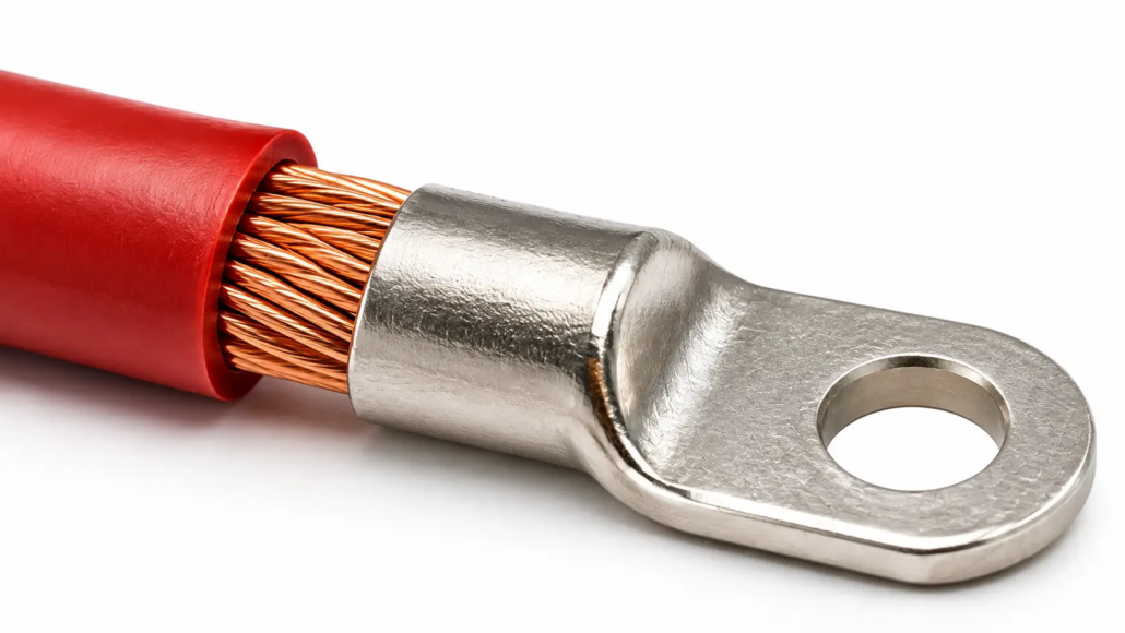
One application involves a stranded copper conductor inserted into a metallic terminal barrel.
Depending on the terminal design, solder may be introduced into the barrel before or during heating. The objective is to establish the specified soldered connection between the conductor and terminal.
The heating arrangement must account for:
•Terminal barrel dimensions
•Conductor cross-sectional area
•Number and diameter of individual strands
•Conductor insertion depth
•Solder entry location
•Distance between the joint and cable insulation
A larger terminal may require a different coil arrangement and heating cycle from a smaller cable lug.
The process should be developed around the actual terminal and conductor combination rather than selected solely according to cable size.
1.2 Copper Wire to Connector Pin Connections
Another application involves joining a copper wire to a metallic connector pin or receiver.
In this arrangement, the stripped wire is inserted into a receiving section of the connector. Solder paste, solder preforms or another suitable filler delivery method may be used, depending on the joint construction.
UltraFlex has published an application involving copper cables soldered to copper pins for aerospace test-system harness manufacturing.
In that particular test, solder paste was applied inside the cable receiver and to the stripped cable end. The induction coil covered the receiver during heating.
This illustrates an important difference from cable lug soldering: the soldering area may be a relatively small receiving section rather than a large terminal barrel.
1.3 Solder-Cup Connectors
Solder-cup connectors use a dedicated cavity or cup to receive a conductor.
The conductor insertion depth, solder quantity and final fill condition must be controlled according to the connector specification.
Some solder-cup assemblies are difficult to inspect visually after joining because the soldered contact is recessed or enclosed.
For these assemblies, inspection and process-control requirements should be established before production.
NASA-STD-8739.4A specifically addresses solder-type connectors and non-removable solder cups, including conductor insertion, solder fill, fillet conditions and alternative inspection methods when the joint cannot be viewed directly.
1.4 Soldering Is Not a Universal Alternative to Crimping
Cable terminal joining methods must be selected according to the terminal design and applicable requirements.
A soldering process should not automatically be added to a conventional crimped power connection.
EPRI’s Electrical Connectors Application Guidelines explain that soldering a conductor before crimping is generally not recommended because solder can introduce additional material and variables into the crimped interface.
The guidelines also identify certain folded-wing terminal designs where soldering after crimping may be specified.
Therefore, induction soldering should only be considered when the terminal manufacturer, product specification and applicable workmanship requirements permit it.
2. Joint Geometry and Solder Placement
2.1 Conductor Insertion and Joint Geometry
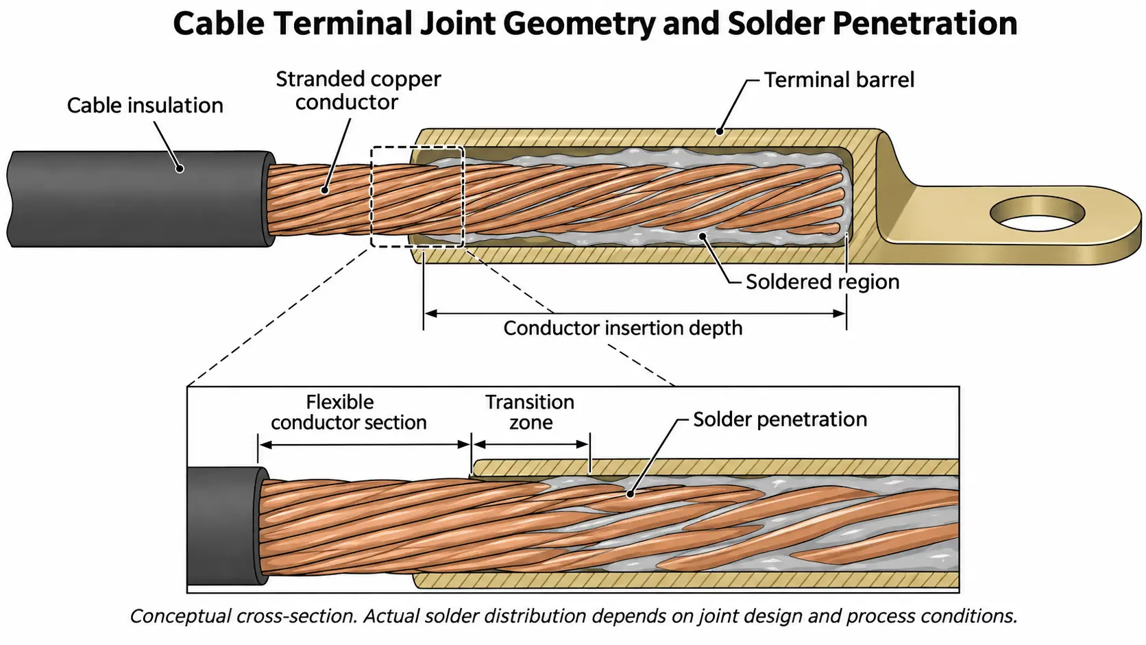
The physical relationship between the conductor and terminal determines the available space for solder.
For a terminal barrel, relevant dimensions include:
•Internal barrel diameter
•External barrel diameter
•Barrel length
•Conductor diameter or bundle dimensions
•Insertion depth
•Distance from the conductor end to the terminal opening
For a solder-cup connector, the receiving cavity and conductor insertion depth become particularly important.
The conductor must be positioned according to the terminal’s specified assembly requirements.
A joint that is too loosely fitted may allow solder to escape or accumulate unevenly. An unsuitable fit may also make solder distribution difficult to reproduce.
However, not every soldered connection relies on the same capillary gap. A cable barrel filled around stranded wire and a connector solder cup are different joint geometries and should be evaluated separately.
2.2 Solder Wire, Preforms and Paste
The filler delivery method should match the joint design and production arrangement.
Solder wire feeding
Solder wire can be introduced into the connection during heating.
This method allows solder quantity and feeding timing to be adjusted during process development.
It may be suitable for terminal barrels or open connection geometries where the filler can be introduced directly into the intended joining area.
Preplaced solder
A measured solder preform can be positioned before heating.
Preforms can help control filler quantity and placement in repeat production, provided the geometry supports stable positioning.
Solder paste
Solder paste combines metallic filler particles with a flux system.
It can be applied to defined surfaces or inside a connector receiver, depending on the product design.
The paste quantity, particle alloy and flux characteristics must be compatible with the application.
These three methods are not interchangeable. The choice depends on the connection geometry, accessibility, production volume and required joint characteristics.
2.3 Solder Flow and Joint Filling
Once molten, solder moves according to surface wetting, joint geometry, gravity and the available flow paths.
For a cable terminal, the direction in which the assembly is positioned can influence how molten solder is retained.
In a published Ambrell application involving a copper grounding lug and wire, the manufacturer used a specially designed two-turn C-shaped coil to concentrate heating on the lug.
The application report also describes how vertical positioning allowed excess solder to flow out of the lower end of a filled lug, while horizontal positioning made it easier to retain solder around the wire and lug.
This is a useful example of how workpiece orientation can affect solder distribution.
The appropriate arrangement must still be determined from the actual terminal design and required solder quantity.
2.4 Controlling Solder Wicking
In stranded conductors, molten solder may penetrate between individual wire strands through capillary action.
This is known as solder wicking.
The resulting soldered section becomes more rigid than the untreated stranded conductor.
If the rigid section extends too far into an area that must remain flexible, bending stresses may concentrate near the transition between the soldered and flexible portions.
NASA-STD-8739.4A addresses this issue by requiring solder wicking to remain outside portions of the wire that need to retain flexibility.
The required solder penetration should therefore be established according to the cable construction and applicable workmanship requirements.
Excessive solder penetration should not be treated as evidence of a better connection.
3. Joint Heating and Cable Insulation Protection
3.1 Heating the Metallic Terminal
An induction coil can be positioned around or near the metallic terminal to generate heat in the intended joining region.
The changing magnetic field induces electrical currents in the conductive workpiece. The resulting resistive heating raises the terminal temperature.
Heat then transfers to the adjoining conductor and solder.
The exact heating pattern depends on the terminal material, dimensions, coil geometry, operating frequency and coupling conditions.
The objective is to bring the intended soldering surfaces to the required process conditions without unnecessarily heating surrounding components.
3.2 Heat Conduction Along Copper Conductors
Copper has high thermal conductivity.
As a result, heat introduced at the terminal can travel along the connected conductor.
This is important because the insulation near the terminal may experience thermal exposure even when the coil is concentrated around the metallic joint.
The heating response is influenced by:
•Cable cross-sectional area
•Number and diameter of conductor strands
•Terminal mass and wall thickness
•Exposed conductor length
•Heating duration
•Distance between the joint and insulation
Different cable constructions can therefore produce different thermal responses under similar nominal heating conditions.
3.3 Protecting Cable Insulation
Cable insulation materials have different temperature limits and thermal response characteristics.
PVC, silicone rubber, XLPE and fluoropolymer insulation should not be treated as having identical thermal behavior.
The process must consider the insulation material’s specified temperature limit and the duration of thermal exposure.
Potential process measures include:
•Concentrating the coil around the terminal
•Maintaining repeatable workpiece positioning
•Controlling heating time
•Selecting a suitable power and frequency range
•Monitoring critical temperatures during process development
•Using appropriate fixtures or thermal protection where permitted
The actual temperature near the insulation should be evaluated during testing.
A terminal surface temperature alone does not establish that the insulation has remained within its allowable thermal exposure.
4. Solder Alloy, Flux and Surface Preparation
4.1 Solder Alloy Selection
Tin-based solder alloys are commonly considered for electrical soldering applications.
Possible alloy systems include:
•Tin-lead alloys, where permitted
•Tin-silver alloys
•Tin-silver-copper alloys
•Tin-copper alloys
The appropriate alloy depends on the required melting range, base-metal compatibility, service temperature, electrical requirements and regulatory restrictions.
The alloy must also be compatible with the terminal’s surface finish.
For example, soldering a plated copper terminal may require different process considerations from soldering an unplated copper component.
The selected alloy should follow the product requirements and solder supplier’s recommendations.
4.2 Flux Selection and Compatibility
Flux helps remove or control surface oxides and supports solder wetting.
Its selection depends on the solder alloy, base material, surface condition and required cleaning procedure.
Important considerations include:
•Flux activity
•Activation temperature
•Compatibility with terminal plating
•Residue characteristics
•Cleaning requirements
•Electrical cleanliness requirements
A flux that performs well on one terminal material may not be suitable for another.
For electrical connectors, flux residue on contact surfaces can be particularly problematic.
4.3 Surface Preparation
Oil, grease, oxidation and other contaminants can interfere with solder wetting.
Before soldering, the terminal and conductor should be prepared according to the approved manufacturing procedure.
Surface preparation may involve suitable mechanical or chemical cleaning methods.
The selected method must not damage the conductor strands, terminal plating or other functional surfaces.
Induction heating does not eliminate the need for proper surface preparation.
4.4 Post-Solder Cleaning and Residue Control
After soldering, flux residue should be evaluated according to the flux manufacturer’s instructions and the applicable connector requirements.
Some flux systems are designed for no-clean processes, while others require cleaning.
For electrical connectors, cleaning is particularly important when residue could reach mating contact surfaces.
NASA-STD-8739.4A identifies flux residue, solder splash, metal flakes and other contamination as materials that must be removed from connector contact surfaces when they may compromise the connector system.
The cleaning process should therefore be selected according to the flux chemistry, connector construction and product specification.
5. Induction Coil Positioning and Process Control
5.1 Matching Coil Geometry to the Terminal
The coil should be designed around the intended heating region and actual terminal geometry.
Different applications may require:
•C-shaped open coils
•Helical coils
•Single-position coils
•Custom-shaped coils for specific terminal assemblies
For a cable lug, an open or specially shaped coil may provide access for solder feeding and workpiece loading.
For a small connector pin, a compact coil may be more appropriate.
The coil configuration should consider terminal dimensions, conductor position, solder location and insulation clearance.
5.2 Controlling the Heating Zone
The active heating region should correspond to the intended soldering area.
If the coil is positioned too far from the terminal, coupling may become less effective.
If the coil heats too much of the adjoining cable, thermal exposure of the insulation may increase.
The objective is to achieve the required joint temperature while limiting unnecessary heating of surrounding materials.
The final coil-to-workpiece clearance and positioning should be established through application testing.
5.3 Temperature Measurement
Temperature measurement should be selected according to the joint geometry and process requirements.
Possible methods include:
— Thermocouples attached at suitable measurement locations.
— Infrared temperature measurement.
— Other validated temperature-monitoring arrangements.
The measurement location is important.
A temperature measured on the outside of a terminal may not represent the temperature at the internal solder interface.
Likewise, a temperature measurement near the insulation does not necessarily indicate the maximum temperature inside the terminal.
The measurement method should be validated against the actual assembly and soldering process.
5.4 Establishing Repeatable Heating Conditions
Power, frequency and heating time should be established through testing with the actual terminal, conductor, solder and flux.
Published induction soldering applications illustrate how widely conditions can vary.
| Published application | Reported conditions |
|---|---|
| Copper grounding lug and wire | 10 kW system, 109 kHz, approximately 188°C, 40 seconds |
| 50 mm² cable and terminal | 2.8 kW, approximately 260°C, 15–20 seconds |
| Copper cables and pins | Approximately 315°C, 2 seconds |
These figures represent separate application tests conducted with different workpiece geometries and equipment configurations.
They are not directly comparable or recommended process settings.
For a production application, the heating cycle should be validated against solder wetting, joint fill, insulation temperature and finished-joint requirements.
6. Common Process Problems and Joint Quality Verification
6.1 Common Problems
| Process problem | Possible cause | Recommended checks |
|---|---|---|
| Incomplete solder filling | Incorrect solder placement, poor wetting or insufficient process heating | Solder quantity, flux, surface preparation and joint temperature |
| Excessive solder overflow | Excessive filler quantity or unsuitable workpiece orientation | Solder feeding and fixture position |
| Excessive solder wicking | Uncontrolled solder flow along conductor strands | Solder quantity, conductor construction and required flexible length |
| Insulation damage | Excessive thermal exposure | Coil position, heating time and insulation temperature |
| Inconsistent joint appearance | Variation in workpiece position or solder feeding | Fixture repeatability and process controls |
| Poor solder wetting | Oxidation, contamination or incompatible flux | Surface preparation and material compatibility |
| Contaminated connector contacts | Flux residue or solder splash | Post-solder cleaning and inspection |
These problems can have different causes even when they produce similar external symptoms.
For example, incomplete filling does not necessarily mean that heating power is too low. It may result from poor surface preparation, unsuitable solder placement or an incompatible flux system.
The cause should be identified before changing the heating parameters.
6.2 Visual Inspection
Visual inspection can help identify:
•Incomplete solder coverage
•Excessive solder buildup
•Poorly formed solder fillets
•Visible contamination
•Damaged insulation
•Solder splash on connector contact surfaces
Acceptance criteria should follow the applicable product specification and workmanship requirements.
6.3 Electrical Testing
Electrical testing may include:
•Continuity testing
•Contact resistance measurement
•Insulation resistance testing
•Dielectric withstand testing, where required
For power connections, contact resistance is particularly important because excessive resistance can result in additional electrical losses and localized heating during operation.
Test methods and acceptance limits should be established for the actual application.
6.4 Mechanical Testing
Mechanical evaluation may include tensile, pull or other application-specific tests.
For flexible cables, the transition between the soldered and unsoldered portions should also be considered.
A connection that meets an initial electrical requirement may still have inadequate mechanical reliability under repeated movement or vibration.
Mechanical testing should therefore reflect the actual service conditions and applicable product requirements.
6.5 Cross-Section Inspection
Cross-section inspection can provide information about the internal solder distribution.
Representative samples may be sectioned to examine:
•Solder penetration
•Distribution around conductor strands
•Unfilled areas
•Internal discontinuities
•Solder penetration toward the insulation
This is particularly useful during process development when the external appearance cannot establish the internal joint condition.
For solder-cup connectors that cannot be visually inspected after assembly, NASA-STD-8739.4A identifies alternative inspection and process-control measures, including interim inspection, X-ray inspection and control of conductor insertion and solder fill.
7. Selecting an Induction Soldering System for Cable Terminals
The equipment configuration should be selected after the terminal construction and required soldering process have been defined.
The following information is useful during application evaluation.
| Application information | Purpose |
|---|---|
| Cable material | Identifies conductor properties |
| Cable cross-sectional area | Helps evaluate thermal mass and heating response |
| Stranded or solid conductor | Influences joint geometry and solder penetration |
| Terminal material | Determines electromagnetic heating characteristics |
| Terminal dimensions | Helps establish coil geometry |
| Terminal plating | Determines solder compatibility |
| Insulation material | Establishes thermal exposure limits |
| Solder alloy | Determines the required soldering temperature range |
| Flux specification | Defines surface activation and cleaning requirements |
| Solder placement method | Determines filler delivery requirements |
| Production quantity | Helps establish the required production arrangement |
| Joint acceptance criteria | Defines the required quality verification |
Depending on the application, the induction system may include:
•Adjustable heating power
•Suitable operating frequency
•Dedicated induction coils
•Temperature monitoring
•Stored process programs
•Workpiece positioning fixtures
•Automatic solder feeding
•Integration with production handling equipment
For repeat production, a dedicated coil and fixture can help maintain consistent workpiece positioning and heating conditions.
The final equipment configuration should be evaluated using representative production samples.
Frequently Asked Questions
Click a question to expand the answer.
Can induction heating be used to solder copper cables to terminals?
Yes. Induction heating can be used for suitable cable terminal assemblies designed for soldering. The metallic terminal is heated, transferring heat to the solder and adjoining conductor surfaces.
How can cable insulation be protected during induction soldering?
The coil should concentrate heating around the intended joint. The insulation material, distance from the heating region and duration of thermal exposure must all be considered.
The actual insulation temperature should be checked against the cable manufacturer’s specifications.
What is the difference between solder wire, solder preforms and solder paste?
Solder wire is generally fed into the joint, preforms are positioned before heating, and solder paste is applied to defined surfaces or cavities. The most suitable method depends on joint geometry, accessibility and production requirements.
Why is solder wicking important in stranded cable assemblies?
Solder wicking can make part of a stranded conductor rigid. If it extends into a region that needs to remain flexible, mechanical stresses may concentrate at the transition. The required solder penetration should be controlled according to the assembly specification.
Can the same induction coil be used for different cable terminal sizes?
Not necessarily. Different terminal dimensions, conductor sizes and soldering locations can require different coil arrangements. The suitability of a coil should be verified using the actual workpiece geometry.
Conclusion
Induction soldering can provide a controlled heating method for suitable cable terminal and electrical connector assemblies.
The quality of the finished connection depends on the relationship between joint geometry, conductor positioning, solder placement, heat transfer and material compatibility.
A reliable process must also account for cable insulation, solder wicking, flux residue and the required electrical and mechanical performance.
For industrial production, the most effective approach is to develop the induction heating process using the actual terminal and conductor assembly, then verify the resulting joint against the applicable product and workmanship requirements.
Technical References
1. NASA-STD-8739.4A – Workmanship Standard for Crimping, Interconnecting Cables, Harnesses, and Wiring
2. EPRI – Electrical Connectors Application Guidelines
3. Ambrell – Soldering Electrical Wire to a Copper Grounding Lug
4. UltraFlex – Induction Soldering of Cables to Terminals
5. UltraFlex – Induction Soldering of Copper Cables to Copper Pins
Need an Induction Soldering Process for Cable Terminals?
Tell us your terminal and cable details, solder alloy and production requirements. Kechuang can help you evaluate the right induction soldering setup for your application.


