Exhaust Valve Seat Induction Hardening Machine
Ⅰ. See Both Machines in Operation
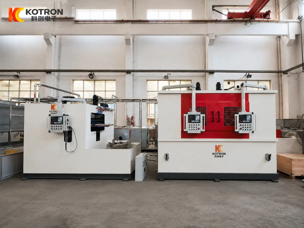
This project uses two different machine configurations for exhaust valve seat induction hardening.
Disc-Type Exhaust Valve Seat Induction Hardening
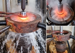
The first video shows the larger valve-seat component on the disc-type machine. The part is supported horizontally on a rotary table, with a large dedicated inductor positioned around the conical working area.
Exhaust Valve Seat Cone Induction Hardening – Vertical Machine
The second video shows the smaller valve-seat specification on the vertical machine. A compact inductor heats the required working area, followed directly by quenching.
Both machines are used for valve seat conical surface hardening, but their workpiece orientation, support method, inductor size and quenching arrangement are different.
Ⅱ. What Surface Is Being Hardened?
The target is the annular conical working surface of the exhaust valve seat.
This surface contacts the mating valve during operation and is repeatedly exposed to contact pressure, impact and wear. Induction hardening concentrates the heat in this working area rather than heating the complete valve-seat body uniformly.
Viewed from above, the treated area may appear to be a narrow circular band. Its actual geometry is a conical annular surface around the valve seat.
The position, width and geometry of this surface matter when designing the inductor and setting up the machine. A change in cone geometry can change the required inductor position even when the overall workpiece diameter is similar.
Ⅲ. Disc-Type Hardening Machine for the Larger Valve Seat
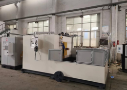
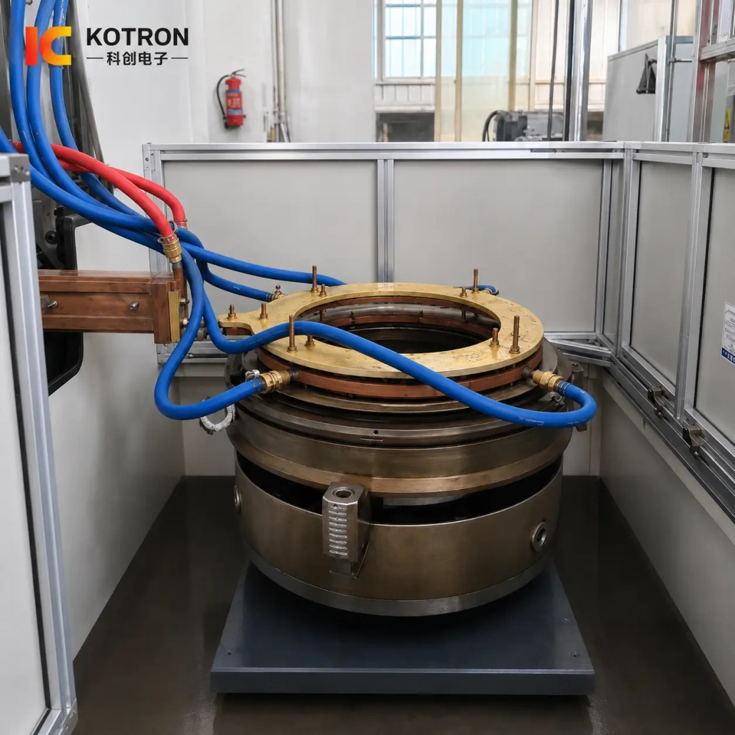
In this project, the larger valve-seat specification is processed on a disc-type rotary hardening machine.
The workpiece is placed horizontally on the rotary worktable. For a large-diameter and relatively heavy component, this arrangement provides direct support from below and a stable rotational axis during processing.
A large circular inductor is positioned above the valve seat. Its effective heating section is designed around the annular conical working area rather than using a conventional straight scanning coil.
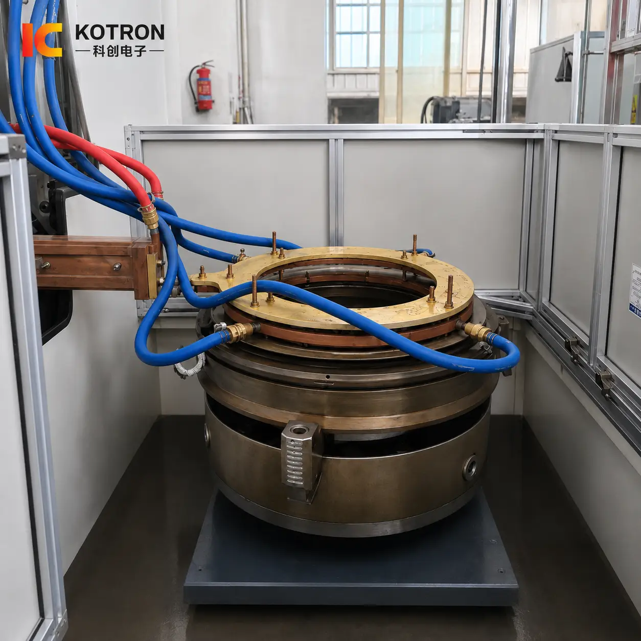
Disc-type exhaust valve seat induction hardening machine
During the hardening cycle, the rotary table controls workpiece rotation while the inductor remains at the required working position.
The machine structure is therefore not simply a larger version of the vertical unit. The worktable, support method, fixture and inductor are all developed around the larger horizontal component.
The relative position between the inductor and the workpiece also needs to remain controlled. On a large circular part, changes in the gap around the circumference can affect electromagnetic coupling and alter the heating pattern.
For this reason, workpiece support and concentric positioning are part of the hardening process, not just mechanical details.
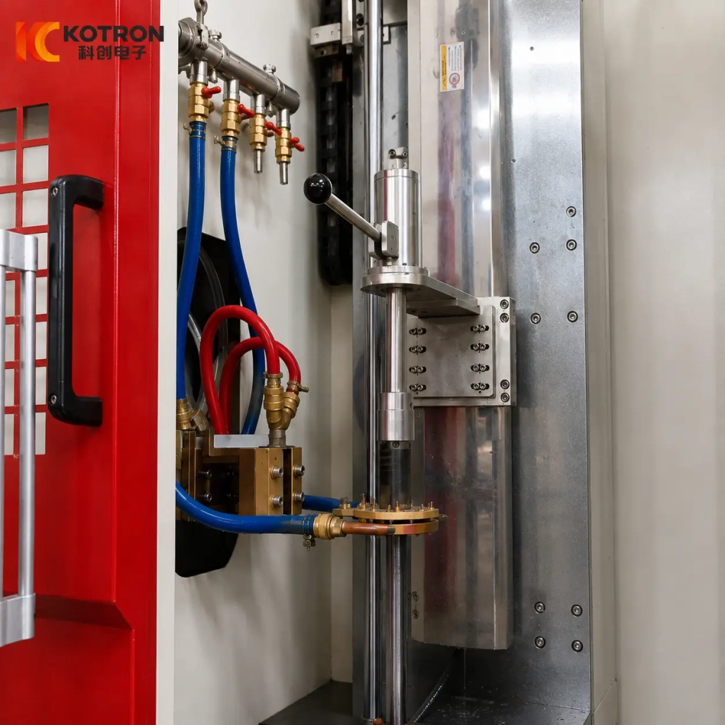
Ⅳ. Vertical Hardening Machine for the Smaller Valve Seat
The smaller valve-seat specification in this project uses a vertical induction hardening machine.
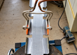
Instead of lying on a large horizontal rotary table, the component is held in a compact vertical processing station. A smaller dedicated inductor is positioned relative to the valve-seat working surface through the vertical mechanism.
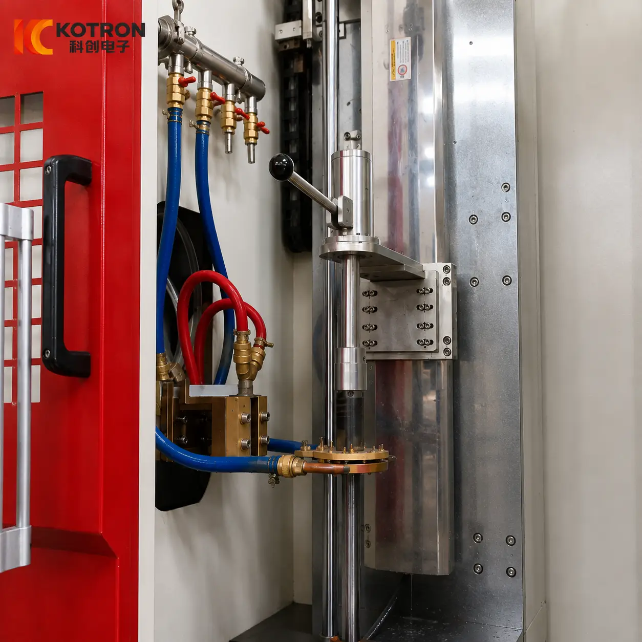
Vertical exhaust valve seat induction hardening machine
The vertical configuration has its own clamping direction, positioning mechanism, inductor dimensions and quenching arrangement.
Its working video also makes the transition between heating and cooling particularly clear. The selected area is first induction heated, and quenching liquid is then applied directly to the same processing zone.
This heating-to-quenching sequence is more important than describing the machine simply as “compact.” The machine structure has been developed around how the smaller part is held, positioned and processed.
It is therefore not just a reduced-size version of the disc-type machine.
Ⅴ. How the Hardening Cycle Is Controlled
Repeatable valve seat hardening depends on several operations being coordinated.
The workpiece must first be positioned and clamped correctly. The inductor then needs to reach its established working position relative to the conical surface.
Several variables work together during the cycle.
Workpiece positioning
The relative position between the valve seat and inductor needs to remain within the established process condition.
Rotation
Workpiece rotation is coordinated with the heating process according to the machine configuration and hardening method.
Power and heating time
Electrical output and heating duration determine how energy is introduced into the working surface.
Inductor-to-workpiece gap
The distance between the effective heating section and the workpiece affects electromagnetic coupling and therefore the heating distribution.
Quenching timing
Cooling follows the heating stage according to the programmed sequence. Delaying or changing this transition can affect the final hardening result.
A typical machine cycle can be summarized as:
Positioning → Clamping → Inductor Positioning → Rotation → Heating → Quenching → Return
The disc-type and vertical machines do not necessarily use identical movement or timing. Their mechanical arrangements are different because the parts themselves are different.
Ⅵ. Inductor Design for the Valve Seat Conical Surface
The inductor is one of the most workpiece-specific parts of this equipment.
A larger outside diameter generally requires a correspondingly different inductor size, but diameter alone is not enough for design.
The following details also matter:
The inductor-to-workpiece gap, sometimes referred to as the coupling gap, deserves particular attention.
The objective is not simply to place the copper conductor as close to the workpiece as possible. The effective heating section needs to follow the required surface with a controlled relationship to the part.
The difference is visible between the two machine configurations. The disc-type machine uses a large circular inductor suited to the larger valve seat, while the vertical machine uses a much smaller inductor matched to its workpiece and processing space.
The conductive sections of the inductor are also water cooled. High-frequency current passes through the copper conductor while electromagnetic induction generates heat in the workpiece itself.
The resulting heating pattern depends on the combination of:
Valve Seat Geometry + Inductor Geometry + Coupling Gap + Power + Frequency + Rotation + Quenching
This is why an actual workpiece drawing is more useful for inductor design than an outside diameter alone.
Ⅶ. IGBT Power, DSP Control and PLC Machine Coordination
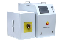
The system combines IGBT induction power conversion, DSP digital power control and PLC machine control.
These functions are related, but they are not the same.
The IGBT power stage performs the high-frequency power conversion required by the induction heating circuit.
The DSP controller manages the induction power supply digitally, including output regulation and operating control. Depending on the power-supply configuration, electrical parameters such as voltage, current, output power and frequency can be monitored during operation.
The PLC coordinates the machine sequence.
This can include:
— Workpiece positioning
— Clamping
— Rotary-table operation
— Inductor movement
— Heating start and stop
— Quenching
— Machine return and interlocking
The heating power supply and mechanical machine actions therefore operate as parts of the same programmed hardening cycle.
Where additional process traceability is required, the system can also be configured with monitoring functions for process parameters, alarms and historical production information.
It is useful to separate these roles clearly:
IGBT — power conversion
DSP — induction power control
PLC — machine sequence control
The objective is not the presence of three control technologies by itself. What matters is that electrical output, workpiece movement and quenching follow the established process consistently from one part to the next.
Ⅷ. Complete Hardening System for Different Valve Seat Specifications
The equipment shown on this page is a complete exhaust valve seat induction hardening system using dedicated machine configurations for different workpiece specifications.
In this project, the larger valve seat is processed on the disc-type rotary machine, while the smaller component is processed on the vertical machine.
The system can include:
The two machines belong to the same hardening project, but this does not imply that they form an automatically interconnected production line.
Their purpose is to cover different valve-seat specifications with machine structures suited to the actual parts.
Can one machine process several valve-seat specifications?
Possibly, within its mechanical and electrical range. Different valve seats may still require separate fixtures, inductors and process settings.
Is the entire valve seat hardened?
No. The hardening process is concentrated on the specified conical working area.
Can the same inductor be used for different valve seats?
Not necessarily. Valve-seat dimensions, cone geometry, hardening position and required heating pattern all influence inductor design.
What information is needed before equipment design?
The most useful starting information is:
Workpiece Drawing
Material
Outer and Inner Dimensions
Weight
Cone Angle
Conical Working Surface
Required Hardening Area
Surface Hardness
Effective Case Depth
Production Requirement
Send Your Exhaust Valve Seat Drawing
Provide your workpiece drawing, material, dimensions and hardening requirements — we will evaluate the machine configuration, fixture, induction power, frequency, inductor and quenching arrangement for your valve seat.