
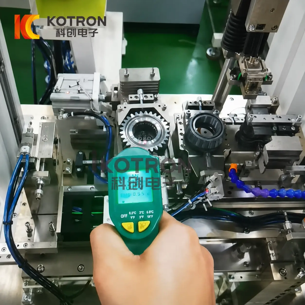
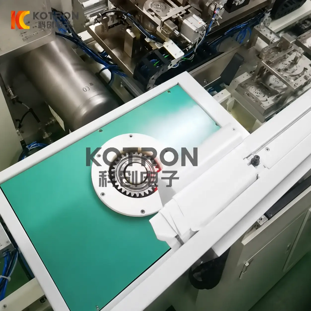
Automatic Induction Shrink Fitting Line
Controlled Induction Heating and Automated Assembly for Interference-Fit Components
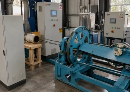
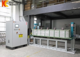
An automatic induction shrink fitting line heats the outer component to create the temporary clearance needed for assembly, then positions and joins the mating parts under a controlled production sequence.
The line can be configured for gears, rotors, couplings, sleeves, hubs and other interference-fit assemblies. Heating stations, inductors, part handling, temperature control and assembly tooling are developed around the actual workpiece rather than a fixed machine format.
Ⅰ. Watch a Gear Shrink-Fitting Line in Operation
This video shows one application of the production line: induction heating and automated assembly of a gear onto its mating component.
The gear application is representative rather than restrictive. The same shrink-fitting principle can be applied to other interference-fit parts when their materials, dimensions, fit and assembly requirements are suitable. For a deeper look at the equipment decisions behind a line like this, see our shrink fitting machine selection guide.
The line handles the complete sequence — from part loading and induction heating through to temperature verification, assembly, cooling and release — so the operator manages the process rather than handling heated components.
Ⅱ. What Can Be Assembled by Shrink Fitting?
Shrink fitting is particularly useful when one component must be mounted over another with an interference fit. Typical assembly relationships include:
Transmission, powertrain, industrial gearbox assemblies — common in automotive manufacturing
Electric motor and generator manufacturing
Pump, compressor and drivetrain connections
General mechanical interference-fit joints
Rolling-element bearing mounting — also see induction bearing removal for disassembly
Ⅲ. How Induction Shrink Fitting Works
A shrink fit starts with an intentional dimensional interference between two mating components. Instead of forcing the parts together at their original dimensions, the outer component is heated so that its bore expands temporarily. The components are then assembled while sufficient clearance exists. As the heated part cools, it contracts around the mating component and restores the designed interference.
This is a standard mechanical joining principle. MIT’s manufacturing course describes a shrink fit as heating one body so that it expands, placing it over the other component, and then allowing it to cool. To understand how the electromagnetic field generates this heat at the component level, read our guide on how induction heating works.
The required temperature is therefore not a fixed machine parameter. It depends on the part dimensions, material thermal expansion, interference, required assembly clearance and process limits.
Ⅳ. Why Use Induction Heating for the Assembly Step?
Induction heating generates heat in electrically conductive material through an alternating electromagnetic field. The U.S. Department of Energy describes industrial induction heating as using electric current to create a magnetic field that heats conductive materials.
For shrink fitting, this makes it possible to concentrate the heating process on the component that needs to expand rather than treating the complete assembly as one heated mass. Compared to gas furnaces or resistance heating, induction delivers energy directly to the part surface where the expansion needs to happen.
The aim is not simply to heat the part as fast as possible. The part must reach the required assembly condition without creating an unnecessary temperature difference or delaying transfer to the assembly station.
Ⅴ. From Heating to Assembly — How the Line Is Configured
A production line is built around the sequence required by the part. Each station — from the induction heating system components to part handling and cooling — is configured to match the workpiece. A typical project may include:
Loading → Positioning → Induction Heating → Temperature Confirmation → Transfer → Shrink-Fit Assembly → Position Confirmation → Cooling → Unloading
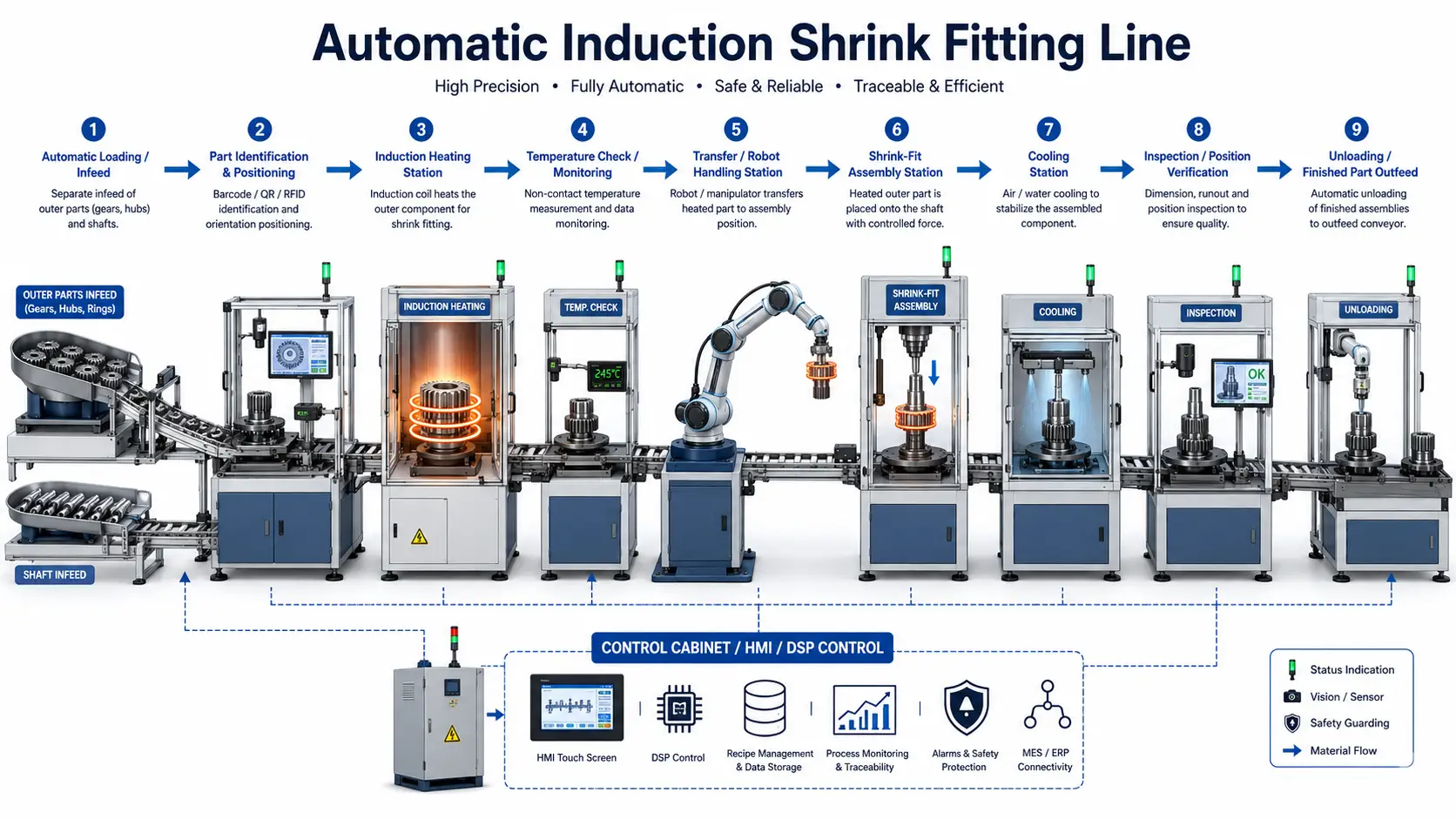
The exact sequence depends on the workpiece. Some applications only require heating and automatic insertion; others may require orientation, controlled transfer, auxiliary pressing, position detection or additional cooling before release.
Inductor and heating method matched to the part that must expand. Coil geometry is especially important where heating needs to be concentrated around a bore, ring or selected section.
Part orientation and transfer must place the heated component onto its mating part before too much assembly clearance is lost during cooling.
Depending on fit and production method, assembly may rely on thermal clearance or use controlled mechanical motion.
After assembly, the fitted component cools until the joint reaches the condition required for subsequent handling.
Ⅵ. Multi-Station Heating for Automatic Production
A single heating station is not always the most suitable arrangement for a production line.
For multi-station applications, the induction heating platform includes time-shared, multi-frequency configurations with multiple load outputs. Individual stations can use different power and frequency settings and can be matched with different induction coils for different workpieces or heating processes. The induction heating generator selection determines how flexibly power can be allocated across stations.
This is useful where a line contains several heating positions, handles different part variants, or needs the heating sequence coordinated with other assembly operations.
It should not, however, be assumed that every line needs multiple outputs. The number of stations is selected from the required cycle, part mix and line arrangement.
Ⅶ. IGBT Power Conversion and DSP Digital Control
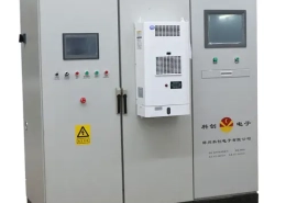
The induction heating section uses IGBT power conversion with DSP digital control. For a detailed comparison of digital control platforms, see our guide on digital induction heating power supplies.
The role of digital control is more important than the component names themselves: the power supply has to follow the heating recipe consistently and exchange operating information with the rest of the line. DSP control provides real-time acquisition of:
The same platform can communicate with centralized control equipment, allowing the heating station to become part of a wider production-line control network.
Where required, heating control can also be configured around constant-current, constant-power or temperature-controlled operation, depending on the selected power-supply and temperature-control package.
Ⅷ. Temperature Control Matters Before the Parts Meet
For shrink fitting, the useful process variable is not simply heater-on time.
The heated component needs enough dimensional expansion for assembly, and that expansion depends on both the material and its temperature. Too little thermal clearance can make assembly difficult; excessive heating may be unnecessary or unsuitable for the component. The same temperature sensitivity applies to related processes like induction normalizing and annealing, where precise thermal control defines the metallurgical outcome.
This is why temperature measurement should be considered together with the induction power setting. Depending on the application, the system may use thermocouple or other suitable temperature feedback, with closed-loop control configured around the production process. Available configurations include power-and-temperature dual closed-loop control, temperature curves and high/low temperature or heating-time alarms.
The actual sensor type and control method should be chosen after the workpiece and heating position are known.
Ⅸ. Process Recipes, Alarms and Production Records
For recurring products, operators should not have to rebuild the heating setup from memory every time a batch returns. With the corresponding monitoring configuration, heating parameters can be stored and reviewed together with operating records.
Available functions include real-time voltage, current and power display, heating curves, upper/lower parameter alarms, historical records, operator information and production-batch data. These functions are part of an optional energy-monitoring platform and should be specified when process traceability is required.
For an automated shrink-fitting line, this data answers practical production questions:
Q: Which recipe was used for this part?
Stored recipe names and parameters linked to each production run.
Q: Did the heating cycle stay within the defined limits?
Upper/lower alarm logs show whether parameters drifted outside the process window.
Q: Was an alarm generated? Which batch was being processed?
Alarms are timestamped and linked to batch and operator records for traceability.
Q: Can a previous heating curve be reviewed?
Historical curves are retrievable for quality review, troubleshooting or customer audit.
Ⅹ. The Inductor and Tooling Are Designed Around the Part
A universal production line does not mean a universal induction coil. The shape of the component, bore position, available heating area, surrounding geometry and required temperature distribution all affect the inductor design. For a detailed look at how coil geometry shapes the heating pattern, see our guide on how induction coils work.
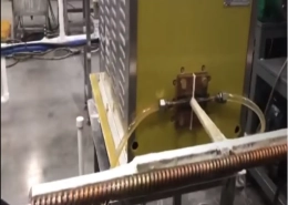
Available inductor forms for fitting and heating work include opening-type, frame-type, adjustable-radius frame, belt, flat and flexible heating arrangements. For an automatic shrink-fitting line, the final coil and fixture are selected around the actual workpiece and automation method.
Part handling deserves the same attention. A gear, rotor and coupling may all use shrink fitting, but their orientation, gripping points, transfer distance and assembly motion can be quite different.
Ⅺ. Fit and Part Data Come Before Machine Selection
The heating system cannot be selected from the outer diameter alone. A useful technical proposal starts with the relationship between the mating components.
| Workpiece Information | Assembly Requirement |
|---|---|
| Part drawing | Required fit / interference |
| Materials of both parts | Assembly position |
| Bore diameter | Required insertion depth |
| Shaft or mating diameter | Orientation requirement |
| Outer dimensions | Production rate |
| Part weight | Allowed process temperature |
| Current assembly method | Automation requirement |
If the mating dimensions are specified using a standard system of limits and fits, providing the actual tolerance designation is preferable to describing the connection only as “tight fit.” ISO 286 defines the system of tolerances, deviations and fits for linear-size features. Where possible, send the actual drawing and interference requirement, not only the nominal shaft diameter.
Ⅻ. Technical Configuration
Because an automatic shrink-fitting line is workpiece-specific, publishing an arbitrary universal power or temperature range would be misleading. A project configuration can instead be defined around the following items:
| Item | Configuration |
|---|---|
| Induction power | Selected according to workpiece and heating cycle |
| Operating frequency | Selected according to part geometry and heating requirement |
| Heating station quantity | Application-dependent |
| Inductor | Customized to workpiece |
| Temperature measurement | Configured according to heating position and process |
| Power control | DSP digital control |
| Multi-station output | Available where required |
| PLC / HMI | Configured to production-line sequence |
| Part transfer | Customized to workpiece and layout |
| Assembly mechanism | Selected according to fit and assembly method |
| Process monitoring | Optional according to traceability requirement |
| Communication interface | Available according to line-control requirement |
Specific power-supply models and mechanical dimensions should be confirmed after the part and production cycle have been evaluated.
ⅩⅢ. Typical Shrink-Fitting Applications
The application should always be assessed from the actual fit, material and geometry rather than from the component name alone.
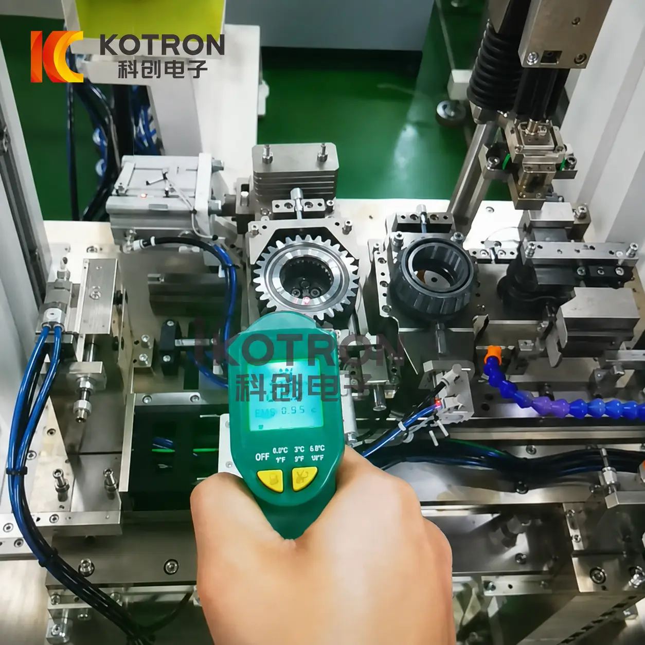
Gear-to-Shaft Assembly
A gear is heated to increase bore clearance, transferred to the assembly position and fitted onto the shaft. This is the application shown in the production video on this page. Gears for transmissions, powertrains and industrial gearboxes are among the most common shrink-fitting candidates — the interference fit transmits torque without keys or splines when designed correctly. For a broader view of induction heating across powertrain components, see our automotive parts buyer’s guide.
Rotor-to-Shaft Assembly
Motor rotors are among the thermal assembly applications for electric motor and generator manufacturing lines. Also see induction heating for wind power components, where generator rotor shrink fitting is a recurring application.
Coupling-to-Shaft Assembly
Induction heating prepares shaft couplings for thermal assembly or disassembly in pump, compressor and drivetrain applications. For removal scenarios, see induction bearing removal — many of the same principles apply.
Bearing & Ring Components
Heating a ring-shaped component before mounting is an established interference-fit technique. Temperature and handling must respect the component manufacturer’s requirements. See also induction heating for large rings for geometry-specific considerations.
Sleeves, Hubs & Similar Fits
Evaluated when geometry and material permit controlled thermal expansion and the line can provide the required positioning and assembly sequence. Related: connecting rod induction heating covers similar interference-fit assembly challenges.
ⅩⅣ. When an Automatic Line Makes Sense
An automatic shrink-fitting line is most useful when the process is repeated often enough for heating, transfer and assembly to be coordinated as one production sequence.
Typical reasons for moving from a standalone heater to a line include:
• Repeated production of the same or related assemblies
• Need for controlled transfer between heating and fitting
• Multiple heating or assembly stations
• Part identification or recipe management requirements
• Need to reduce manual handling of heated components
• Production records or traceability requirements
• Integration with upstream or downstream equipment
For occasional maintenance assembly or field disassembly, a standalone induction heating system may be more appropriate than a complete automatic line. Portable induction heaters and air-cooled systems are available for field fitting and unfitting work — those systems serve a different purpose than the automated production-line product on this page.
ⅩⅤ. Frequently Asked Questions
What information is needed to select the heating power?
Does shrink fitting always eliminate pressing force?
Can one line assemble more than one product?
Can the heating temperature be controlled automatically?
Can several heating stations use different settings?
Can production data be recorded?
Is the line only for gears?
ⅩⅥ. Send Us the Two Mating Parts
A useful shrink-fitting proposal starts with both sides of the assembly. Please provide:
✓ Workpiece drawings
✓ Materials
✓ Bore and shaft dimensions
✓ Tolerances or interference amount
✓ Required assembly position
✓ Part weight
✓ Current assembly method
✓ Required production rate
✓ Available factory layout
✓ Automation and data-recording requirements
From these details, the induction heating station, power and frequency, inductor, temperature-control method, transfer mechanism and assembly sequence can be evaluated together.
Related Products
Click here to add your own text


