
9 Critical Factors for Induction Heating Large Rings: Mastering Power, Coil Design & Process Control
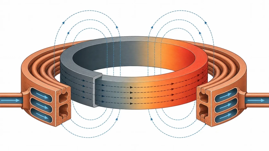
Induction heating for large rings looks easy on a process sheet. Heat a steel ring to temperature, hold, quench or assemble. On the shop floor, it doesn’t play out that way.
A 2-meter bearing race weighs hundreds of kilograms. The coil gap that worked on the 300 mm prototype opens up when you scale to the full part. The turntable bearing has 3 mm of runout, so the coupling gap wanders every revolution. By mid-shift the cooling water inlet has drifted 4°C and the power supply starts folding back.
None of this is on the part print. But it all comes out in the hardness pattern, the cycle time, and the reject rate.
This article covers what actually matters: why you size the power supply around the heated zone rather than the part weight, why frequency and coil type can’t be chosen separately, what makes temperature uniformity hold or fall apart, and why the mechanical handling side often decides whether the electrical design succeeds at all.
1. Why Large Rings Are Challenging to Heat
A ring spreads its mass over a wide diameter. Even a modest wall section adds up to a lot of heated volume, and the geometry fights you on two fronts.
First, the circumference is long. Keeping temperature even from one side of the ring to the other isn’t trivial. Second, the radial width and wall thickness create their own gradients. The OD sits at temperature while the ID still lags. Or the surface overshoots before the mid-wall catches up.
Then there’s the handling. A ring gear for a wind turbine yaw bearing can weigh over a ton. You can’t slide it into a coil by hand. The fixture has to locate it repeatably, the turntable has to spin it smoothly, and the coil has to survive thermal expansion, the occasional bump, and thousands of cycles. If the part is awkward to load, operators will load it inconsistently. Inconsistent loading, inconsistent heating.
Distortion catches engineers off guard, too. Large rings are less stiff relative to their diameter than compact parts. Uneven heating means uneven expansion, which can ovalize the ring before it reaches temperature. A few millimeters of distortion might not scrap the part, but it shifts the coil-to-part gap enough to change the heating pattern mid-cycle.
2. Common Applications for Large Ring Induction Heating
Large ring heating shows up wherever circular parts exceed roughly 500 mm in diameter. But the process goal drives everything.
— Ring gear and bearing race hardening — surface or contour hardening of gear teeth, raceways, and roller paths, where case depth and pattern control are the primary concerns
— Slew bearing and slewing ring heat treatment — large-diameter bearings for cranes, excavators, and wind turbines, often requiring through-hardening or induction hardening of specific raceway zones
— Shrink fitting of sleeves, couplings, and flanges — thermal expansion for assembly, where the ring must reach a uniform expansion temperature without overheating, scaling, or losing dimensional stability
— Preheating before welding or cladding — bringing large pipe rings, flanges, or pressure vessel sections to preheat temperature before welding operations
— Stress relieving of fabricated rings — low-temperature soak cycles to reduce residual stress after welding or machining
— Brazing of ring assemblies — localized heating of braze joints on circular assemblies without heating the entire component
— Pre-forge heating of rolled ring blanks — bringing ring preforms to forging temperature for subsequent rolling or sizing operations
— Repair and rework heating — localized heating of large rings in the field, such as bearing removal or thermal straightening
A shrink-fit cycle wants uniform through-heating and slow, controlled expansion. A gear hardening cycle wants a precise case depth profile and rapid quench response. The power supply and coil that nail one will miss the other. For an overview of the underlying physics, see how induction heating works.
3. Power Supply Selection for Large Ring Heating
The most expensive mistake? Buying a power supply by part weight.
Weight tells you the total thermal mass. It says nothing about where the heat needs to go, how fast it needs to get there, or how much power you’ll lose between the output terminals and the part surface. Start with the heated zone instead: the volume of material that must hit target temperature within the cycle. For through-heating a bearing ring, that’s the entire cross-section. For case hardening a ring gear, it might be the outer 3 mm of the tooth flanks and root. The required part power follows from specific heat, heated-zone mass, temperature rise, and allowed heat time.
But here’s the catch. Coupling efficiency between the coil and a large ring rarely exceeds 70–75% in production. If the coil gap is generous to accommodate part variation, efficiency can drop below 60%. A 150 kW heating demand at the part can need a 250 kW power supply at the input.
Beyond the kW number, the supply needs the right frequency range for the ring size and wall thickness, enough duty cycle headroom for the production cadence, and a load-matching range wide enough to handle the impedance swing as the ring heats and its magnetic properties shift. For a deeper discussion on sizing, see power selection for induction heating.
Matching power to production rate
Higher throughput pushes the power requirement up. If a ring must reach 850°C in 90 seconds instead of 4 minutes, the power demand scales almost proportionally. But the thermal gradients don’t scale the same way. A short, aggressive cycle can create a steep surface-to-core delta that may or may not be acceptable.
For lower volumes, a longer soak at lower power often produces better uniformity and gives the controls more time to respond. The tradeoff is cycle time versus installed electrical cost and utility demand charges. In practice, the decision usually comes down to whether the heating station is the bottleneck (spend on power) or downstream ops are (save on power, run a longer cycle).
4. Frequency Selection and Heating Depth
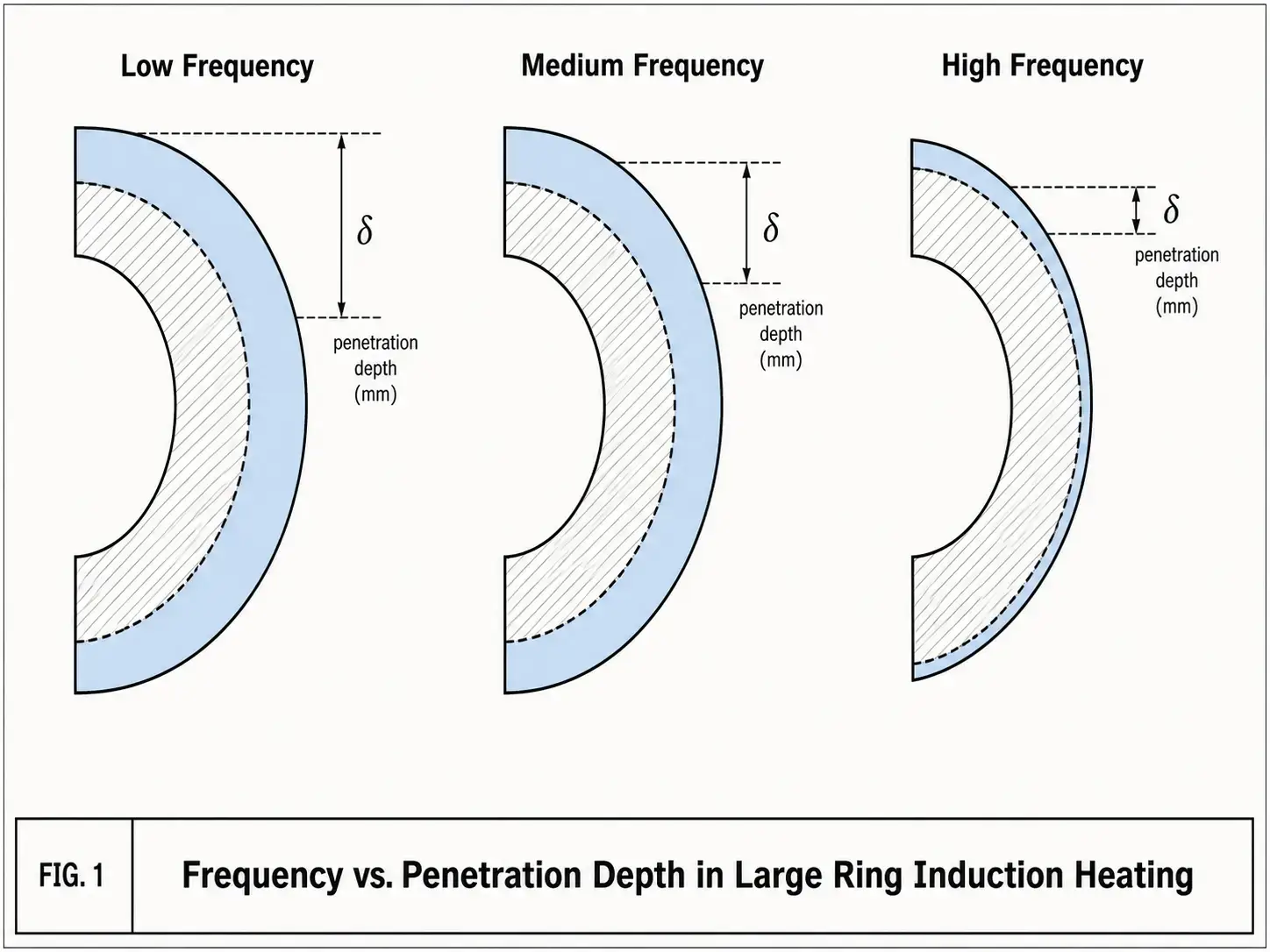
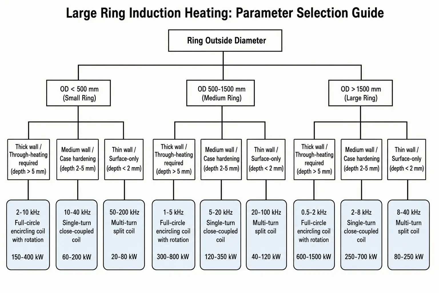
Frequency determines how deep the induced current penetrates before it decays to about 37% of its surface value — the reference depth δ. Lower frequencies, deeper heating. Higher frequencies, shallower. For large rings, the decision tree has three branches: surface-only, case-depth-limited, or full through-heating.
Here’s how the bands map to real results in steel rings:
| Frequency Range | Typical Penetration Depth (steel, hot) | Best Suited For |
|---|---|---|
| 1–10 kHz (Low / Medium) | 5–15 mm | Through-heating thick rings, deep case hardening, shrink fitting of heavy sections |
| 10–50 kHz (Medium / High) | 1.5–5 mm | Ring gear hardening, bearing raceway hardening, general case depth applications |
| 50–400 kHz (High) | 0.3–1.5 mm | Shallow surface hardening, thin-wall rings, fine tooth profiles, localized braze heating |
Two more things matter in practice. One: as steel crosses the Curie temperature (around 770°C), it goes non-magnetic and the penetration depth jumps. A frequency that gave you shallow heating during the magnetic phase will suddenly punch deeper. That can help for through-heating and hurt for precise case depth control. Two: frequency and coil geometry are tied at the hip. A given frequency behaves one way in a large-diameter encircling coil, another way in a small scanning coil. Pick them together or don’t bother. See frequency selection for induction heating for more detail.
5. Coil Design Options for Large Rings
A coil that delivers the right power and frequency on paper can still fail in production. Awkward to load. Hard to keep cool. Too sensitive to part positioning. For large rings, the coil is usually the single biggest lever on process performance.
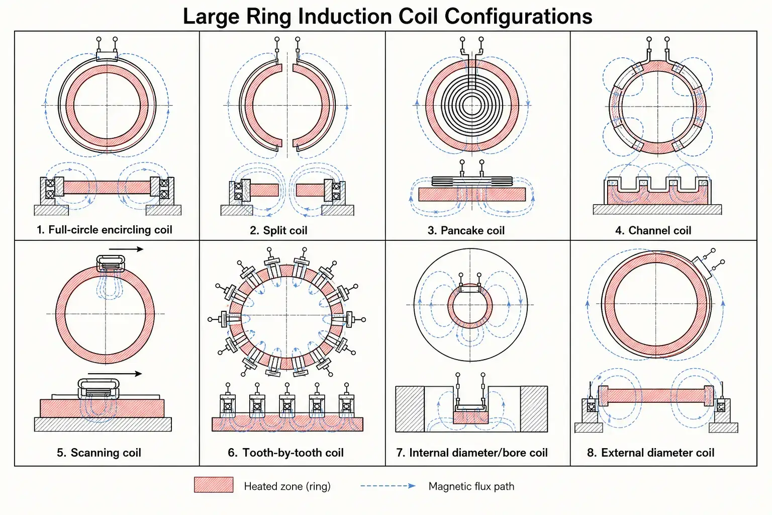
The coil-to-part gap deserves its own conversation. A tight gap improves coupling and cuts power demand. A wider gap makes loading forgiving and tolerates part variation. For production rings with mill tolerance on diameter, the gap has to accommodate the largest ring in the batch without contact. Minimum practical gap: 1.5–3 mm for precision-ground rings, 4–8 mm for as-forged or rough-machined. Every extra millimeter costs you 3–8% in coupling efficiency, more at higher frequencies.
Don’t forget thermal expansion. A 2-meter steel ring at 900°C grows roughly 20–25 mm in diameter. The coil either accommodates that growth or the cycle finishes before the gap closes to zero. For more on the principles behind coil design, see induction coil design.
6. Temperature Uniformity and Process Control
For a ring gear headed for hardening, ±15°C around the circumference separates a consistent HRC 58–60 pattern from scattered results and soft spots. The causes are usually mechanical, not electrical.
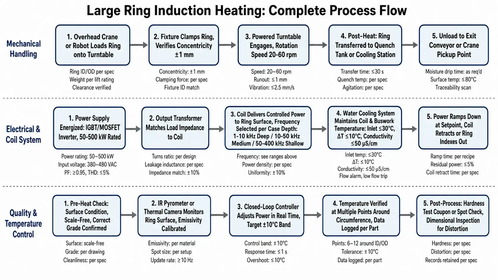
Coil gap varies because the ring isn’t perfectly round or centered. The turntable bearing has runout. The ring was loaded a few millimeters off. Rotation is the standard fix — it averages out local variation in coupling, gap, and heat loss. Target 20–60 rpm for rings under 1.5 meters, slower for larger diameters to keep surface speed manageable. Too slow, you get discrete hot and cold zones. Too fast, the fixturing gets expensive.
Temperature measurement deserves realistic expectations. IR pyrometers depend on emissivity, and emissivity changes with surface condition, scale, temperature, and viewing angle. A pyrometer calibrated on clean ground steel reads wrong on a scaled ring. Thermal cameras show more but cost more and need a clear sight line. The most reliable path: validate the pyrometer or camera against embedded thermocouples during process development, lock the recipe, then use the non-contact sensor for production monitoring within the proven window.
Closed-loop power control helps when incoming part temperature varies or cooling water drifts through a shift. But it won’t fix a bad coil or sloppy positioning. If the coupling varies 20% around the circumference, no control loop will produce a uniform result. Uniformity starts with the coil and the fixture. The controls just refine what those deliver. See common induction hardening defects for what happens when uniformity breaks down.
7. Mechanical Handling, Rotation, and Automation
On large ring systems, the handling equipment often costs more than the power supply and coil combined. It also determines whether the process runs the same way at 4 PM on Friday as it did during commissioning on Tuesday morning.
One trap to watch for: conductive fixturing too close to the coil. Steel fixtures, clamps, or roller supports inside the magnetic field will heat unintentionally, stealing power from the part and distorting the heating pattern. Use non-conductive or low-conductivity materials — ceramics, low-permeability stainless steels, or water-cooled copper shields — for anything near the coil. For a broader look at system integration, see how to select an induction hardening system.
8. Cooling, Utilities, and System Reliability
Large ring heating pushes water cooling harder than most induction applications. A through-heating cycle for a heavy ring can run minutes, not seconds — and during that entire time the coil, buswork, output transformer, and power supply all need uninterrupted cooling.
Water quality isn’t negotiable. Keep conductivity below 50 μS/cm for high-frequency systems, below 100 μS/cm for medium and low frequency. Dissolved solids plate out on hot copper over time, narrowing flow passages and building up insulating scale. A closed-loop chiller with proper filtration and conductivity control avoids the slow degradation that open-loop systems suffer. It costs more upfront but pays for itself in coil life and uptime.
Before integration, pin down these numbers:
— Total cooling water flow rate across all circuits (power supply, transformer, buswork, coil, and any cooled fixtures)
— Supply water temperature and allowable temperature rise per circuit
— Minimum supply pressure at the system inlet, accounting for hose and fitting losses
— Coil pressure drop at the design flow rate (undersized coil passages are surprisingly common)
— Hose diameter, length, and quick-connect type for each circuit
— Flow switches, temperature switches, and leak detection interlocks wired into the power supply safety circuit
For more detail, see water cooling systems for induction heating.
Specification Readiness Scorecard
Before sending an RFQ to induction equipment suppliers, run through this checklist. The more items you can answer with real data rather than estimates, the better the quotes — and the fewer surprises at commissioning.
☐ Ring material grade and condition (as-forged, normalized, quenched-and-tempered, etc.)
☐ Outside diameter, inside diameter, wall thickness, and face width — with tolerances
☐ Part weight and the weight of the specific heated zone (not always the same thing)
☐ Target temperature with tolerance band (e.g., 850°C ±10°C)
☐ Required heating depth or case depth, if hardening
☐ Target cycle time per part (heat time + quench + load/unload)
☐ Production rate required (parts per shift or per hour)
☐ Available plant power (voltage, phases, kVA capacity, and whether a dedicated transformer is feasible)
☐ Cooling water availability: flow rate, temperature, pressure, and whether a dedicated chiller is needed
☐ Floor space and crane capacity at the planned installation location
☐ Part loading method (crane, robot, forklift, manual with assist)
☐ Quench method and medium, if hardening (polymer, oil, water, spray ring, immersion tank)
☐ Hardness specification: target hardness, effective case depth, acceptable pattern limits, distortion tolerance
☐ Automation and data logging requirements (PLC interface, recipe storage, traceability per part)
☐ Applicable industry standards or customer-specific process specifications
Score 13–15: You have a well-defined specification. Suppliers can provide accurate proposals with firm performance commitments.
Score 8–12: The major parameters are defined, but some gaps remain. RFQ responses will include assumptions that should be reviewed carefully before ordering.
Score 0–7: The process isn’t defined enough yet for a reliable equipment proposal. Expect suppliers to ask more questions than they answer, and build contingency into both budget and timeline.
If the ring has a history of problems — soft spots after hardening, cracking, excessive runout, inconsistent case depth — include those details in the RFQ. Suppliers can often trace the failure pattern back to the root cause and address it in the system design. For hardening-specific issues, see induction hardening process overview and common induction hardening defects.
Key Takeaway
Induction heating for large rings rewards the engineers who design the whole process, not the ones who buy a power supply and hope. The right combination of power, frequency, coil geometry, part rotation, and cooling produces a repeatable, efficient system. The wrong combination — even with individually well-specified components — produces scrap, downtime, and a process that operators work around instead of with. Start from the ring: its material, its tolerances, and what it needs to become. Engineer outward from there.
FAQ
What size induction heating power supply is needed for large rings?
Size by the heated zone, not the part weight. A 200 kg medium-carbon ring to 900°C in 3 minutes needs 80–120 kW at the part. After 25–35% coupling losses typical for large rings, the nameplate rating lands at 150–200 kW. For thick-walled rings, add soak time rather than cranking power — the surface-to-core delta will punish you otherwise.
How do you improve temperature uniformity on a large ring?
Three things move the needle most: minimize coil-to-part gap variation through better centering and turntable bearing quality; rotate the ring fast enough for multiple revolutions within the heat time (20–60 rpm for rings under 1.5 m); validate your temperature sensor against embedded thermocouples during process development rather than trusting an uncalibrated pyrometer.
Can induction heating be used for large ring gear hardening?
Yes. Spin hardening works for smaller ring gears where tooth tips and roots can reach temperature together. For large ring gears with coarse teeth, tooth-by-tooth or contour hardening makes more sense — it heats each tooth or tooth space individually, avoiding the tip overheating that spin hardening causes on large modules.
Is a closed-loop water cooling system worth it for large ring heating?
If the system runs more than a few hours a day, absolutely. Open-loop water plates dissolved minerals onto hot copper surfaces, raising coil resistance and temperature over time. A closed-loop chiller with conductivity below 50 μS/cm, proper filtration, and a heat exchanger sized for the total heat load pays for itself in coil life, uptime, and process consistency.
Discuss Your Large Ring Heating Application
Share your ring dimensions, material, target temperature, and production requirements. Our engineering team can help evaluate power supply size, coil concept, heating method, and automation options for your process.


