
Induction Heating in Oil & Gas Pipe Manufacturing: 7 Applications and 6 Engineering Decisions That Determine Success
An API 5L X65 pipe with a 24-inch OD and 18 mm wall needs its end heated to 1,150°C for upsetting. The line runs 40 joints per shift. A gas furnace takes 20 minutes to bring that end to temperature and another 15 to stabilize between loads. An induction heating oil & gas pipe system does it in 90 seconds, heats only the last 300 mm, and the operator does not wait for a furnace to recover between cycles. That is the difference. It is not about technology preference — it is about whether the heating step sets the pace of the entire mill, or keeps up with it.
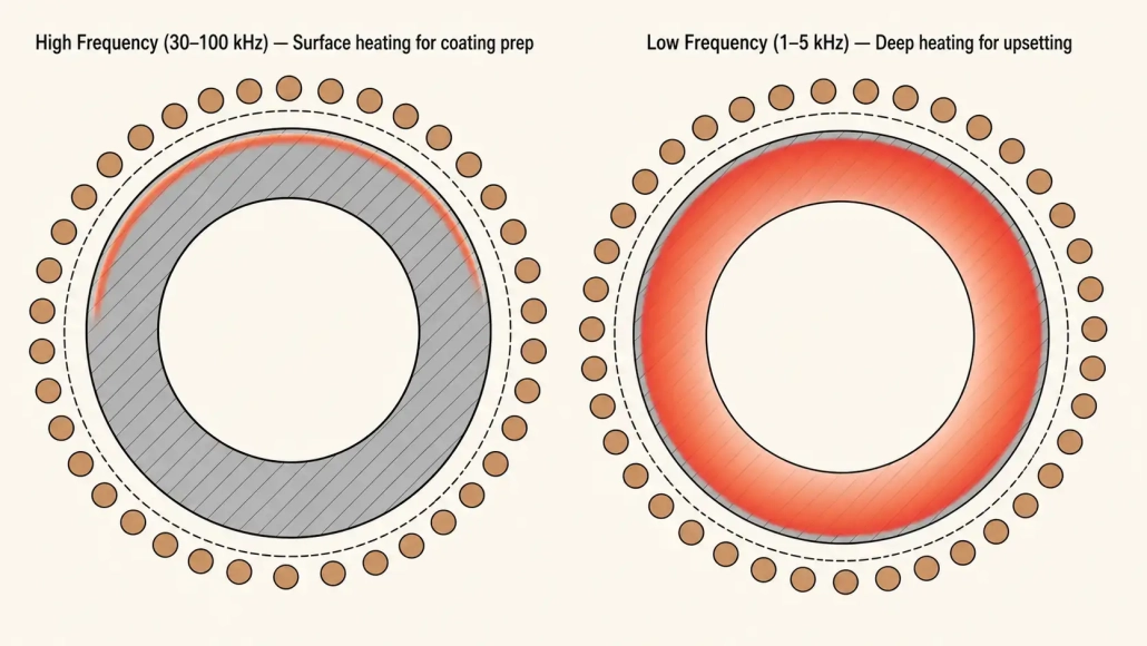
Oil and gas pipe manufacturing confronts heating equipment with an unusual combination: diameters from 2 inches to over 48 inches, wall thicknesses from a few millimeters to 60 mm in heavy-wall seamless, alloy grades designed to resist sour service or deepwater collapse, and line speeds that leave no room for process drift. Induction heating handles these demands when the system is engineered around the specific pipe — not when a catalog power supply is dropped onto the mill floor with a generic coil.
Table of Contents
1. Why Induction Wins for Pipe: Speed, Control, and Floor Space
Pipe mills are space-constrained and throughput-obsessed. A gas furnace large enough to heat 40-foot pipe sections occupies 15 to 25 meters of line length and idles at 15–25% of rated energy consumption even when no pipe is in it. An induction coil for the same job occupies roughly 2 meters — the coil itself plus the buswork — and draws zero power when the line stops. A 500 kW medium-frequency system brings a 12-inch schedule 80 carbon steel pipe end from ambient to 1,100°C in under 60 seconds. The same pipe in a gas furnace needs 12–18 minutes, plus another 8–12 minutes for the furnace to recover its setpoint after the door opens.
Three factors tip the decision toward induction:
- Heating is localized. You heat the weld seam, the pipe end, or the coating surface — not the entire 12-meter joint. This reduces energy input, limits metallurgical changes away from the target zone, keeps the rest of the pipe cool enough to handle, and eliminates an open flame near downstream solvent-based coating operations.
- Temperature control is closed-loop. Pyrometers aimed at the heated zone feed temperature data back to the power supply in milliseconds. When line speed changes or a new pipe diameter enters the coil, the system adjusts power before the pipe exits the coil. Gas furnaces respond in minutes.
- Integration with automation is direct. Induction systems communicate with conveyor drives, rotation systems, and plant-level PLCs. The heating recipe changes with the pipe part number — not with manual burner adjustments between product changeovers.
2. 7 Induction Heating Applications in Pipe Production
Induction is not one heating application in a pipe mill. It shows up at the weld station, the coating line, the end-forming cell, the heat-treat bay, and the brazing bench. Each application demands a different combination of frequency, power density, coil geometry, and temperature uniformity. The table below maps the 7 most common ones.
| Application | Typical Temp | Frequency Range | What Makes or Breaks It |
| Weld seam PWHT | 600–750°C | 3–30 kHz | Heating band width must cover HAZ without overheating base metal; coil-to-seam alignment ±2 mm |
| Pipe end heating for upsetting / forming | 1,050–1,250°C | 0.5–5 kHz | Heated length control (±5 mm); through-wall uniformity before the forming press closes |
| Coating / lining preheat | 60–120°C | 10–100 kHz | Surface temperature uniformity ±5°C; pipe must rotate through coil; line speed 10–60 m/min |
| Stress relieving (localized) | 550–680°C | 1–10 kHz | Soak time verification; thermal gradient at transition zone; insulation band placement |
| Full-body normalizing | 850–950°C | 0.5–3 kHz | Through-wall uniformity across entire length; multi-zone or scanning required for pipes over 6 m |
| Preheating before welding | 150–350°C | 5–50 kHz | Heat band placement ahead of weld torch; consistent temperature at arc strike point |
| Brazing of fittings, collars, sensors | 600–900°C | 50–400 kHz | Localized heat to the joint only; filler metal flow control; avoiding heat damage to adjacent seals or coatings |
3. Diameter, Wall Thickness, and Material Grade
- Diameter. Pipe OD in oil and gas runs from 2 inches (60 mm) for instrumentation lines to over 48 inches (1,220 mm) for transmission mains. The coil must be larger than the largest pipe that passes through it — plus clearance. A coil built for 6-inch pipe cannot heat 24-inch pipe, period. But a coil sized for 48-inch pipe heating a 6-inch pipe runs at poor coupling efficiency because the air gap is enormous. Mills that process a wide diameter range often maintain multiple interchangeable coils — one for small-bore, one for mid-range, one for large-bore — rather than trying to make one coil cover everything. This is the same challenge covered in our article on induction heating large rings, where diameter range drives coil inventory decisions.
- Wall thickness. Wall thickness dictates heating time, frequency, and whether you need single-sided or through-wall heating. API 5L pipe ranges from Schedule 10 (2.8 mm at small diameters) to Schedule 160 (up to 60 mm for heavy-wall seamless). Thin-wall pipe — under 5 mm — heats fast but overheats faster. A 2-second dwell-time error at 1,200°C can push the inner surface past the material’s upper critical temperature before the pyrometer registers the overshoot on the outer surface. Heavy-wall pipe — above 20 mm — presents the opposite problem: the surface reaches target while the inner wall lags 150–200°C behind. Solving this requires lower frequency, longer soak time, staged heating with multiple coils, or a soak station after the main heating coil.
- Material grade. Carbon steel (API 5L X42–X80, AISI 4130/4140), stainless steel (316L, duplex 2205), and corrosion-resistant alloys (Inconel 625, 825 cladding) each respond differently to induction. Carbon and low-alloy steels heat efficiently below the Curie point (~770°C) because they are magnetic — eddy currents concentrate in a thin surface layer and hysteresis adds extra heat. Above Curie, they become nonmagnetic and heating slows. Stainless steels and nickel alloys are nonmagnetic at all temperatures. They need higher power density or longer heat time to reach the same temperature as a carbon steel pipe of identical dimensions. A system sized for X65 carbon steel may fall 30–40% short on output when switched to duplex 2205 without a power increase.
4. Frequency and Power: Matching the Electrical Side to the Mechanical Side
| Wall Thickness | Typical Application | Recommended Frequency | Why |
| 2–6 mm | Coating preheat, thin-wall ERW preheat | 30–100 kHz | Shallow penetration keeps heat at surface; fast response for high line speeds |
| 6–15 mm | Pipe end forming, weld seam PWHT | 5–30 kHz | Balanced depth — heats through wall with moderate soak; good coupling on mid-range diameters |
| 15–30 mm | Heavy-wall end heating, localized stress relief | 1–5 kHz | Deep current penetration; thermal conduction bridges remaining wall thickness |
| 30 mm+ | Full-body normalizing, thick-wall seamless | 0.5–3 kHz | Maximum penetration depth; often requires staged coils or soak zone for uniformity |
Power must cover the worst case, not the average. Frequency selection follows wall thickness — the table above and frequency guide cover the depth-frequency relationship. Power is sized next: A common selection error is sizing the power supply for the most common pipe size and material, then discovering that the heaviest-wall, largest-diameter, highest-production-rate product in the mix cannot reach temperature at line speed. The power calculation should start from the product that needs the most kilowatts — typically the maximum diameter × maximum wall thickness × fastest line speed combination the mill runs — and add 15–20% margin for coil aging, line-voltage variation, and future product additions.
For reference: heating the last 300 mm of a 24-inch OD, 20 mm wall carbon steel pipe end from ambient to 1,100°C at 20 joints per hour requires roughly 500–700 kW. At 40 joints per hour the same application needs 1.0–1.4 MW. Sizing for the average product and discovering the worst-case joint cannot reach temperature before the forming press closes is the most expensive way to learn this lesson.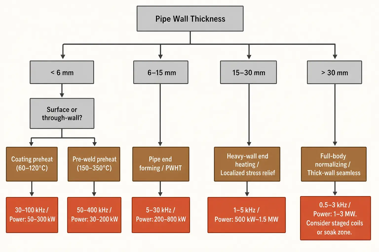
5. Coil Design: Clearance, Cooling, and Mill-Floor Reality
Clearance is the hardest number to hold. Tight clearance improves coil design efficiency, but pipe is never perfectly straight, round, or centered at production speed. A 48-foot joint of 16-inch pipe sags 6–10 mm in the middle. Ovality adds another 2–5 mm. A coil designed with 3 mm clearance on paper will strike the pipe on the first production joint. Production coils run 8–20 mm radial clearance. The efficiency penalty at 8 mm vs. 4 mm on a 12-inch pipe at 3 kHz is roughly 5–8% — a power supply cost increase of $15,000–$30,000. A coil strike that shuts the line down for 4 hours costs more.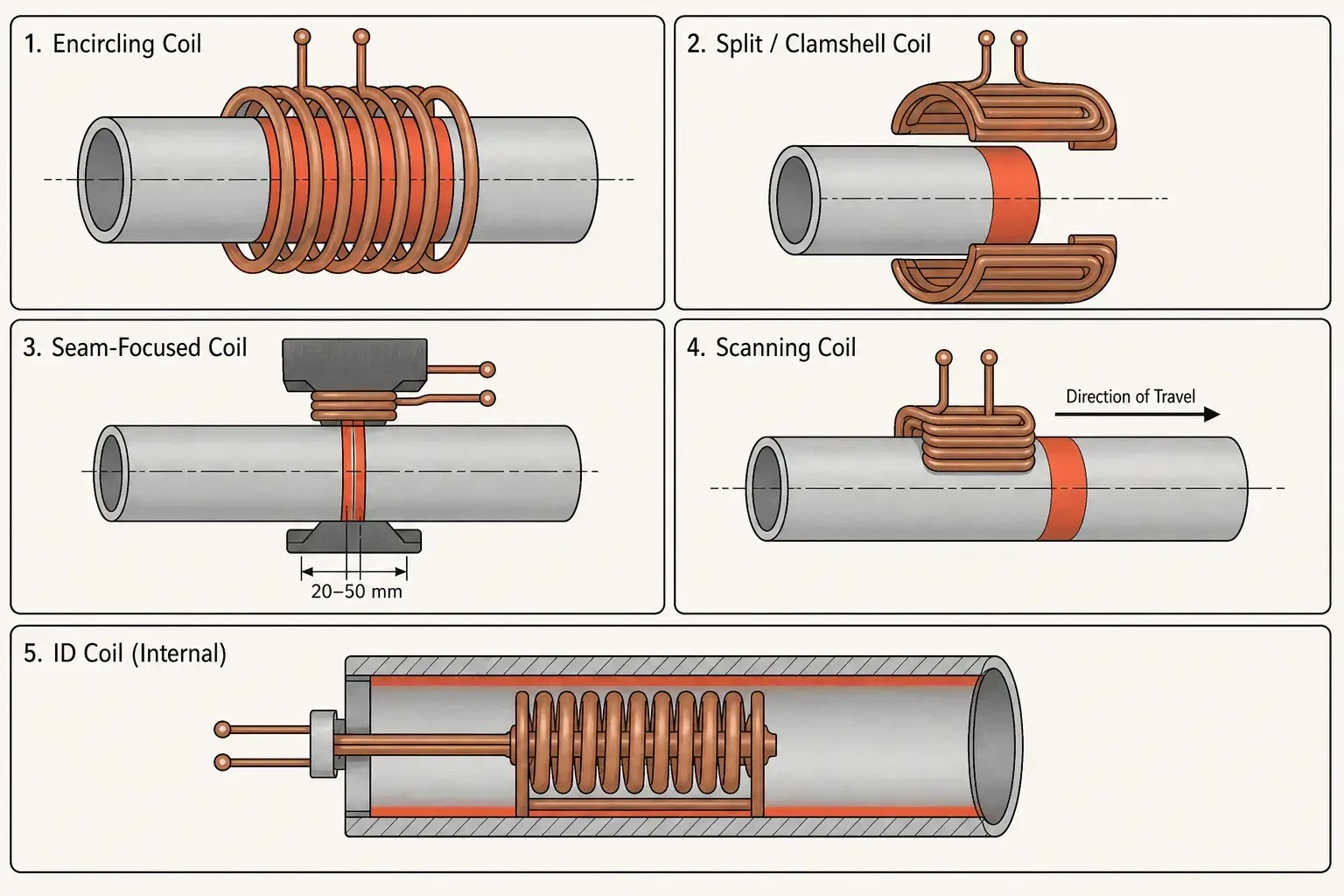
Cooling water must run reliably for 6,000+ hours per year. Induction coils carry thousands of amps — without adequate water flow, copper reaches oxidation temperature in seconds. The water cooling system for a pipe mill coil circulates 40–120 L/min through the coil alone, plus flow for the power supply, capacitors, and buswork. Water quality: conductivity below 300 µS/cm, pH 6.5–8.0, suspended solids under 10 mg/L. Redundant pumps, flow switches per circuit, and conductivity monitoring are production-duty minimums. A cooling failure that takes down the coil often cascades into a capacitor-bank failure if protection circuits are slow.
6. Temperature Control, Rotation, and Line Integration
A pipe mill is not a laboratory. The induction system operates between a blast-cleaning station and a coating booth, or between a saw and a forming press, or between two weld stations. It must start when the pipe arrives, reach temperature before the pipe exits, and stop or ramp down if the downstream equipment faults. Every second the heater waits for the line costs throughput.
- Closed-loop temperature control uses infrared pyrometers aimed at the pipe surface. The control loop adjusts power within 50–100 ms of a temperature deviation. Accuracy depends on surface emissivity — a pyrometer calibrated on clean pipe reads 30–50°C low on scaled pipe. For critical processes like pipe end upsetting above 1,100°C, dual-wavelength pyrometers reduce emissivity error. Single-wavelength units work for coating preheat at 60–120°C where repeatability matters more than absolute accuracy.
- Pipe rotation improves circumferential temperature uniformity. Without rotation, the top of a horizontal pipe runs 30–80°C hotter than the bottom in an encircling coil because of natural convection inside the coil and slight coil-to-pipe eccentricity. Rotation at 20–60 RPM — driven by roller beds on either side of the coil — reduces this differential to 5–15°C. For coating preheat, 5°C circumferential variation is typically acceptable. For upsetting, 15°C variation can produce inconsistent material flow in the forming die. The rotation mechanism must handle the full pipe diameter and weight range, maintain consistent surface speed, and survive in an environment with scale, dust, and occasional coolant spray.
- Line integration means the induction system communicates with everything around it. When upstream equipment stops, the heater ramps to idle — typically 5–10% of rated output — keeping the coil and capacitors warm for sub-2-second full-power recovery when the line restarts, without overheating stationary pipe. Line-stop logic, part-in-place sensors, and automatic reject diversion for out-of-spec sections are standard. Data logging at 1–10 Hz captures power, temperature, line speed, alarms, and recipe changes for every meter of pipe. When a coating failure or weld rejection surfaces three shifts later, the heating record answers definitively.
7. 6 Pipe Heating Problems and How to Prevent Them
Induction heating is repeatable when the system matches the pipe and the process. When it does not, the same failure modes appear across different mills, pipe sizes, and applications. The table below catalogs the 6 most frequent ones.
| Problem | Root Cause | Prevention |
| Uneven circumferential temperature | Coil eccentricity, no rotation, pipe ovality, inconsistent surface condition | Verify coil centering for each diameter change. Add rotation at 20–60 RPM. Check temperature with handheld pyrometer at 4 points around circumference during commissioning. |
| Overheated pipe ends (end effect) | Electromagnetic field concentration at pipe edge; coil extends beyond pipe end | Position pipe end inside coil by 10–20% of coil length from coil edge. Ramp power down in last 5–10 seconds of heating cycle. Use flux concentrators at coil ends. |
| Surface hot, inner wall cold | Frequency too high for wall thickness; insufficient soak time | Lower frequency per Section 4 table. Add soak station between heating coil and next operation. Verify inner-wall temperature with contact probe during process qualification — do not assume surface reading represents through-wall. |
| Excessive scale / oxidation | Too much time above 800°C in air; heating cycle longer than needed | Shorten heat time by increasing power density. Reduce peak temperature where process allows. Consider argon or nitrogen shield gas for critical applications. Remove heavy scale before coating. |
| Coil strike / mechanical damage | Insufficient clearance, bent pipe, roller wear, misaligned guides | Design for 8–20 mm minimum radial clearance. Add entry and exit guide rollers within 500 mm of coil face. Inspect coil ID for contact marks weekly. Keep a spare coil on the shelf. |
| Temperature drift during production | Pyrometer lens fouling, coil cooling degradation, line-voltage variation, component aging | Clean pyrometer optics daily. Monitor coolant temperature and flow trends — rising ΔT across the coil indicates fouling or reduced flow. Verify temperature calibration with a reference pyrometer weekly. |
For deeper diagnosis of uneven heating and pattern-related defects, see our troubleshooting guide and the common induction hardening defects reference.
8. Selecting a System: Questions a kW Rating Cannot Answer
Buying an induction heating system for pipe manufacturing starts with a power rating, but the power rating is the answer to a question that cannot be asked until the pipe range, production rate, and temperature requirement are defined. The supplier’s job is to convert your process into their electrical specification. Yours is to make sure they have the right process information — and to evaluate what surrounds the power supply, because the power supply is never the part that fails first.
Before requesting a quotation, pin down these inputs:
- Pipe OD and wall thickness range (minimum and maximum, not just the most common)
- Material grades — include the hardest-to-heat alloy
- Target temperature and tolerance
- Heated length or pattern (end-only, full-body, seam band)
- Production rate for the worst-case product
- Temperature uniformity requirements (circumferential and through-wall)
- Available electrical service and cooling water specs
- Space constraints, pipe handling direction, and automation interface
When comparing suppliers, weight these above the kW number:
- Pipe heating experience. A supplier with 200 gear-hardening installations may underestimate clearance, straightness, and handling requirements specific to pipe. Ask for references with similar diameter and wall thickness ranges.
- Coil construction and cooling system scope. Does the quote include the heat exchanger, pump skid, filtration, and conductivity monitoring — or just the power supply and coil? A turnkey cooling system adds 20–35% to equipment cost but eliminates the most common early-life failure mode.
- Controls, data logging, and recipe management. A system that cannot store recipes by pipe part number or log process data for traceability wastes setup time on every product changeover and leaves no paper trail when a coating or weld fails three shifts later.
- Commissioning support and service access. Supplier process development on your floor, with your pipe, at your production rate. Plus local spare parts inventory and service response time. A 72-hour response on a line running 20 shifts per week turns a $500 IGBT failure into a $150,000 downtime event.
Key Takeaway
Induction heating oil & gas pipe systems replace furnaces on the mill floor because they heat faster, occupy 2 meters of line length instead of 20, and integrate directly with automated handling. The technology is mature. What determines success is whether the system was engineered around your actual pipe range — diameters, wall thicknesses, material grades, and line speed — or ordered from a catalog. The kW rating answers question five. Pipe geometry, target temperature, and production rate answer questions one through four.
FAQ
Q: What is induction heating used for in oil and gas pipe manufacturing?
A: Pipe end heating for upsetting and forming, weld seam post-weld heat treatment, coating and lining preheat, localized stress relief, preheating before welding, and brazing of attached fittings. The same technology shows up at six different stations in a fully equipped pipe mill.
Q: Can induction heat thick-wall pipe all the way through?
A: Yes — with the right frequency and enough time. Wall thicknesses above 20 mm need frequencies in the 0.5–5 kHz range. The surface reaches temperature first, and thermal conduction finishes the job. For walls above 30 mm, staged heating with two or three coils in series (each at a progressively lower power density) or a dedicated soak station after the main coil produces better through-wall uniformity than trying to do it in a single coil at maximum power. Verify inner-wall temperature with a contact probe during process qualification.
Q: Why does my pipe heat unevenly around the circumference?
A: Three usual suspects: the pipe is not centered in the coil, the pipe is not round, or the pipe is not rotating. Check coil centering first — a 3 mm eccentricity on a 12-inch pipe produces a 25–40°C temperature difference between the near side and far side. Add rotation at 20–60 RPM if not already present. If the problem persists, check for roller wear that lets the pipe settle off-center. Ovality above 2% of diameter also causes circumferential variation that rotation alone cannot fully correct.
Engineering a Pipe Heating System Starts With Your Worst-Case Product
If you are heating 8-inch schedule 160 at 30 joints per shift — or 48-inch X80 at 2 meters per minute — the coil geometry, frequency, and power look completely different. Tell us your pipe OD range, wall thickness range, material grades, target temperature, and line speed. We will spec the heating system around the product that demands the most — not the one that makes the spec sheet look easy.


