
5 Induction Heating Failures — and the Electromagnetic Effect Behind Each One
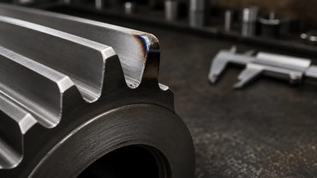
The spline tip melted. Not the whole tooth — just the last 0.5 mm at the corner. The hardness spec was right, the power setting was right, and the coil was centered. But that corner still burned. If that sequence sounds familiar, you have already met one of the five electromagnetic effects that quietly control every induction heating failure before the operator ever touches a control.
These five effects — sharp edge, skin, proximity, ring, and slot — are not textbook trivia. They determine where current actually flows in every coil and every workpiece, on every cycle. Push current where it does not belong, you get a melted corner. Pull it away from where it should be, you get a cold part and a missed cycle time. Five failures below. Each one maps to one effect.
1. Edge Burning at Corners and Spline Tips
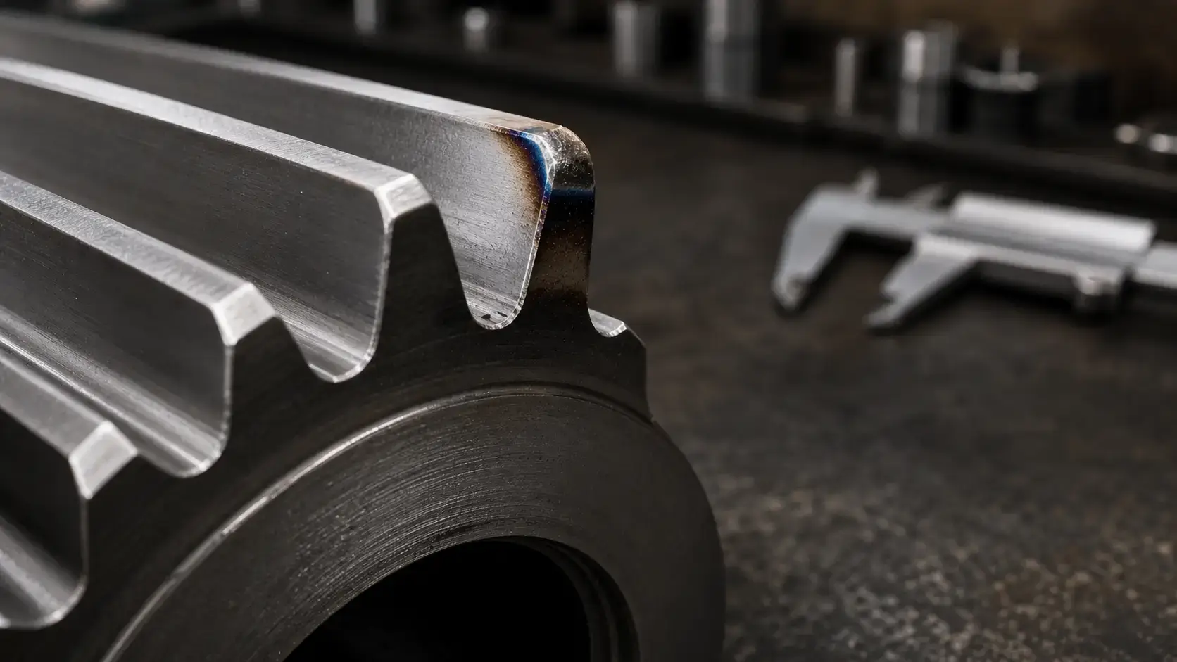
The part comes out of the coil and the corner is rounded over — not machined that way, melted that way. Keyway edges, spline tips, and gear tooth corners are the usual victims. The rest of the surface is fine. Hardness checks pass. But that one corner is gone, and the part is scrap.
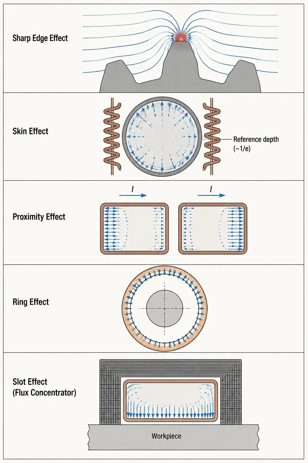
This is the sharp edge effect. Magnetic field lines converge at features with small radii of curvature. Where the lines bunch up, current density spikes. The corner runs hotter than the adjacent flat surface — sometimes wildly hotter — and the operator does not see it until the part exits the coil. More power makes it worse. The root cause is geometry, not the kW setting.
This failure pattern is distinct from the broader category of common induction hardening defects like soft spots or quench cracking — edge burning is localized to a geometric feature every time.
Fix it:
— Add a copper shield or a steel robber block adjacent to the sharp feature. It gives the field somewhere else to go.
— Increase the coil-to-workpiece gap at the corner by profiling the inductor locally.
— Reduce power density in edge-adjacent zones — either by widening the coupling gap or by using a lower-power soak segment in the cycle.
— For critical geometries, pulsed heating lets thermal conduction smooth the temperature gradient between pulses.
2. Case Depth Consistently Off-Target
The hardness profile comes back from the lab and case depth is 1.2 mm. The spec says 2.0–2.5 mm. You change the power, change the scan rate, bump the soak time — and case depth moves by 0.1 mm. It is the kind of result that sends a process engineer down a parameter-tuning rabbit hole for two shifts.
The parameter you are actually fighting is skin effect. Alternating current does not distribute uniformly through a conductor — it crowds toward the surface. The reference depth — the distance at which current density falls to about 37% of its surface value — is called skin depth. It depends on frequency, material resistivity, and magnetic permeability. Higher frequency shrinks the skin depth. Lower frequency pushes it deeper.
If case depth is stuck shallow no matter what you do with power and time, you are running a frequency too high for the target depth. The current physically cannot reach deep enough to heat the material past the reference depth at any practical power level. Frequency selection is the lever here, not more kilowatts.
Fix it:
— Calculate the required skin depth for your target case. If the reference depth is less than half your target case depth at the Curie temperature, you need a lower frequency.
— For deep case depths (>3 mm), move from medium frequency (10–30 kHz) to low frequency (3–10 kHz).
— Resistivity and permeability change with temperature. Steel above Curie becomes non-magnetic and skin depth jumps — your frequency choice must account for both states.
3. Uneven Heating in Multi-Turn Coils
You are running a multi-turn coil and the heating pattern has stripes — hot bands and cold bands alternating along the part axis. The turns are mechanically identical, the spacing looks uniform under a ruler, and the power supply is steady. It should heat evenly. It does not.
What you are seeing is the proximity effect at work against you. When two parallel conductors carry alternating current in the same direction, the current concentrates on the outer sides of both conductors — away from each other. In a multi-turn coil, adjacent turns push current to their outer edges. The workpiece-facing side of each turn gets less current density than the designer assumed. The result is a scalloped heating profile: peaks where each turn faces the part directly, valleys in the gaps between turns.
The proximity effect interacts with coil geometry in ways that are invisible to the naked eye. Two coils with identical outer dimensions and turn count can produce completely different heating patterns if turn spacing differs by even a few millimeters.
Fix it:
— Reduce the turn-to-turn gap. Closer turns force more current to the inner face of each turn through mutual coupling.
— Switch to a single-turn coil if power density and inductance allow it. No adjacent turns, no proximity effect.
— Use flux concentrators on the outer side of each turn to push current back toward the workpiece-facing surface.
4. OD Coil Struggles While ID Coil Doesn't
Two jobs, same power supply, same frequency. The internal bore coil heats the part in 12 seconds. The outer diameter coil on a similar-diameter part takes 20 seconds and runs hotter doing it. The operator compensates with more power, which stresses the coil, shortens its life, and still does not hit the cycle time target. Nothing looks wrong. The coil is centered and the gap is consistent.
The invisible variable is the ring effect. In a circular conductor carrying alternating current, current density concentrates on the inner surface of the ring — the side with the smaller radius of curvature. For an ID coil heating a bore, the ring effect is an ally: it naturally pushes current toward the workpiece-facing surface. For an OD coil heating a shaft, the ring effect is an enemy: it pulls current toward the coil’s inner surface but away from the part, reducing coupling efficiency.
Adding more kW just heats the coil faster. To get current onto the workpiece-facing surface, you redirect it — and that is where flux concentrators earn their cost. A shaped magnetic material on the non-working surface of the OD coil provides a low-reluctance path that forces current back toward the workpiece. Laminated silicon steel works for lower frequencies; ferrite or moldable magnetic composites handle higher frequencies.
Fix it:
— Add flux concentrators to the outer (non-working) surface of OD coils. This is not optional for efficient OD heating — it compensates for the ring effect.
— For ID coils, the ring effect already helps. Do not over-concentrate — leave the design as-is unless heating is too aggressive.
— When switching a coil design from ID to OD application, expect a 15–30% drop in coupling efficiency without concentrators.
5. Slow Heating Despite Correct Power Settings
The power supply reads 80 kW. The frequency is right, the coupling gap is right, and a similar job on a different coil ran fine at 60 kW. But this part crawls to temperature. Cycle time stretches. You run the coil on the bench and it gets hot — hotter than it should — while the workpiece barely moves.
Current is flowing, but it is flowing on the wrong side of the conductor. Without flux concentrators to steer it, alternating current in a rectangular conductor distributes across all four faces — only one of which faces the workpiece. The other three faces heat air, heat the coil housing, heat everything except the part. This is the flip side of the slot effect: when a conductor is surrounded on three sides by magnetic material, current is forced toward the one open side. When that magnetic material is absent, current spreads freely to non-working surfaces.
The symptom is easy to misdiagnose because the power supply shows energy leaving the cabinet. It is going somewhere — just not into the workpiece. The coil runs hotter than expected, cycle times drift upward, and nobody thinks to check whether current is flowing on the right face of the copper.
Fix it:
— Surround the three non-working faces of the conductor with flux concentrator material. The slot effect will crowd current toward the open, workpiece-facing side.
— If you already have concentrators and heating is still slow, inspect them. Cracked, delaminated, or overheated concentrators lose permeability and stop steering current.
— Match concentrator material to frequency: laminated silicon steel below 30 kHz, ferrite above, moldable composites for complex 3D geometries where stacking laminations is impractical.
Key Takeaway
Most induction heating failures are not random. They are predictable. Each one traces back to one of five electromagnetic effects that govern where current goes — and where it does not. Learned as a checklist, they turn a two-shift troubleshooting exercise into a five-minute diagnosis.
If you are setting up a new induction hardening process and the heating pattern does not match expectations, run through the five before changing a single process parameter. The problem is almost always which face of the copper the current is on.
FAQ
Q: How do I tell whether the problem is the coil or the power supply?
A: Swap the coil. If the problem follows the coil, it is geometry or concentrator-related — one of the five effects in this article. If the problem persists with a known-good coil, check the power supply output waveform, bus connections, and matching network.
Q: Can two effects work against me at the same time?
A: They usually do. An OD coil heating a shaft with sharp shoulders and no flux concentrators is losing efficiency to the ring effect, the sharp edge effect, and the missing slot effect simultaneously. Fix them one at a time, starting with the one causing the worst result — usually the sharp edge burning or the deepest efficiency loss.
Q: Are these effects specific to induction hardening?
A: No. The same five effects govern every induction heating application — brazing, shrink fitting, tempering, billet heating, through-hardening. The failure symptoms change by process, but the electromagnetic root cause is identical.
Dealing with a Heating Failure You Cannot Diagnose?
Send us your part drawing and a photo of the failed area. We will tell you which effect is working against you and what the coil needs to fix it.


