
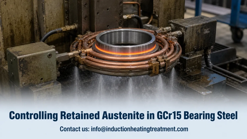
Controlling Retained Austenite in GCr15 Bearing Steel: 6 Process Levers That Actually Work
When a batch of induction-hardened GCr15 bearing rings comes back for dimensional instability six months after shipping, the metallurgical root cause is almost always the same: retained austenite in GCr15 bearing steel that nobody measured. The hardness spec was met. The part looked fine under shop lighting. But in service, it drifted — and now you own a quality problem that hardness testing alone could not catch.
Retained austenite is not a metallurgical mystery. It is a predictable consequence of how you spheroidize, heat, quench, and temper. This article walks through six process levers that control it — from the incoming microstructure to the final verification step — so you can keep RA below 6% without guessing and without shipping parts you cannot stand behind.
1. Spheroidizing: It Starts Before Hardening
The fight against retained austenite begins before the part ever sees an induction coil. A properly spheroidized microstructure — fine, spherical carbides evenly distributed in a ferrite matrix — dissolves carbon uniformly during austenitizing. No carbon-rich pockets. No stubborn austenite islands that refuse to transform.
A poor starting structure — lamellar pearlite, coarse carbides, or carbide networks — creates exactly those pockets. Carbon dissolves unevenly, local austenite stability rises, and after quenching you find RA where the microstructure was never right to begin with.
Practical targets before hardening:
— Post-spheroidizing hardness: ≤190 HB
— Spheroidization quality: fine, uniform carbide distribution per applicable standards
— Incoming microstructure: check it. Every batch. If you cannot measure the structure going in, you cannot control the structure coming out.
2. Induction Heating: Speed, Frequency, Temperature
The induction hardening step is where retained austenite is either locked in or kept out. Three parameters interact, and getting any one of them wrong can undo the work of a good spheroidizing job.
Heating rate. Very high heating speeds create steep thermal gradients across the case. Carbides dissolve unevenly. Localized carbon-rich zones form — and those zones become retained austenite after quenching. A controlled ramp adds seconds to the cycle but saves hours of troubleshooting.
Frequency. For GCr15 bearing steel, medium frequency in the 1–10 kHz range is the practical choice for most parts. Above 50 kHz, current penetration shallows and the thermal gradient sharpens — useful for certain shallow-hardening jobs, but not ideal when RA control is the priority. For a deeper explanation of how frequency affects heat pattern, see our guide on frequency selection for induction heating.
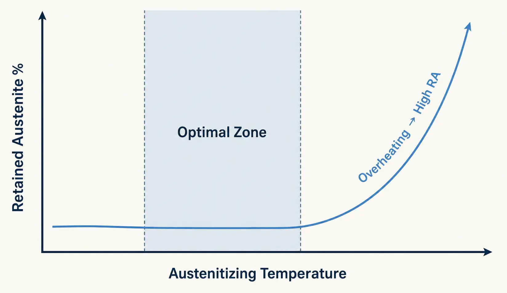
Austenitizing temperature. The practical window for GCr15 is around 820–860°C — but the exact setpoint must be validated on the actual part geometry and heating time, not copied from a general reference.
| Parameter | Recommended Range | Too High → | Too Low → |
|---|---|---|---|
| Austenitizing temp | 820–860°C (validate on actual part) | ↑ carbide dissolution, ↓Ms, ↑ retained austenite | Incomplete carbide dissolution, insufficient hardness |
| Frequency | 1–10 kHz (MF) for most bearing parts | Shallow penetration, steep gradient, localized C-rich zones | Deep but slow heating, may not reach target temp uniformly |
| Heating rate | Controlled ramp, avoid thermal shock | Uneven carbide dissolution, carbon-rich zones → ↑RA | Longer cycle time, but RA risk is lower |
3. Quench Cooling: Fast & Uniform, Not One or the Other
GCr15 has a martensite start temperature around 210°C. The quench must push the part through the critical range fast enough to drive martensite formation and suppress diffusion-controlled products. PAG-type polymer quenchants and fast quenching oils are the common choices — but the medium matters less than how it is delivered.
What actually drives quench consistency on the shop floor:
— Quench delay. Every second between coil-off and quench-on lets the surface temperature drop unevenly. Minimize it.
— Spray pattern. A patchy spray creates hot spots that cool too slowly — and those spots retain more austenite.
— Flow rate and agitation. Enough volume to extract heat, enough turbulence to break the vapor blanket.
— Part orientation. How the part sits in the fixture determines which surfaces see quenchant first.
— Cycle-to-cycle repeatability. A quench that works on the setup part must work identically on part number 10,000.
Fast quenching that is uneven is not fast quenching — it is selective austenite retention built into your process. The quench system must be designed as part of the hardening station, not bolted on after. For guidance on matching the quench system to the process, see our article on selecting an induction hardening system.
4. Tempering: One Cycle Is Rarely Enough
Standard low-temperature tempering at 160–200°C preserves hardness well — but it does very little to reduce retained austenite. If RA control matters for your bearing application, tempering must be treated as a process variable, not a standard step.
A higher range around 220–260°C drives more austenite decomposition while the hardness penalty is often modest — a point or two of HRC in exchange for meaningful dimensional stability. Multiple cycles (two or three) consistently outperform a single cycle because each pass transforms additional retained austenite and stabilizes the structure further.
| Approach | Temperature | RA Reduction | Hardness Impact | Best For |
|---|---|---|---|---|
| Standard single | 160–200°C | Minimal | Negligible — hardness preserved | General-purpose bearings, RA not critical |
| Elevated single | 220–260°C | Moderate | 1–2 HRC loss typical | RA-sensitive, moderate precision requirements |
| Multiple elevated | 220–260°C, 2–3 cycles | Significant | Modest — each cycle adds some loss | High-precision, dimensional stability critical |
| Sub-zero + temper | -70 to -80°C before temper | Maximum | Minimal — martensite formed from RA | ≤3% RA targets, aerospace, premium bearings |
The best tempering schedule is the one validated against your three constraints: hardness requirements, dimensional stability targets, and fatigue performance. If you are only checking hardness after tempering, you are missing two-thirds of the story.
5. Sub-Zero Treatment: When the Target Is Below 3%
For bearing applications where retained austenite must stay below 3% — aerospace, precision spindles, critical-service conditions — sub-zero treatment is the most direct path. Cooling the part to -70 to -80°C immediately after quenching transforms a meaningful fraction of retained austenite into martensite before tempering even begins.
The trade-off is real. Sub-zero treatment adds cost, cycle time, dedicated equipment, and an extra process step that must be controlled and documented. For high-volume standard bearings, it is rarely justified. For premium applications where a dimensional drift in service is unacceptable, it is often the difference between a qualified part and a returned part.
The decision is not metallurgical — it is commercial. If your customer’s specification says ≤3% RA and your tempering alone cannot get there, sub-zero is not optional.
6. Verify: Hardness Alone Tells You Nothing
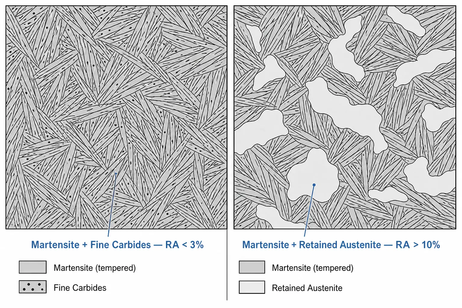
A part can meet its hardness specification and still carry 12% retained austenite. Hardness and RA are different properties measured by different methods — and assuming hardness is a proxy for RA is how out-of-tolerance parts ship to customers.
X-ray diffraction is the reference method for direct RA measurement. Metallographic examination provides visual confirmation of the microstructure. Dimensional stability testing validates what happens in service. For critical parts, fatigue testing closes the loop.
If RA control is a customer requirement — or if you have learned through returns that it should be — measure it on production parts, not just during process development. The cost of XRD testing is trivial compared to the cost of a batch rejection. For more on what goes wrong when hardening processes are not validated, see our guide on common induction hardening defects.
7 Mistakes That Drive Retained Austenite Up
— Skipping incoming microstructure checks. If you do not know what the structure looked like before hardening, you cannot troubleshoot what comes out.
— Overheating during austenitizing. Every degree above the validated setpoint pushes more carbon into solution and lowers Ms.
— Heating too fast with poor uniformity. Thermal gradients create localized carbon-rich zones. Those zones become RA.
— Quench delay. Every second between coil-off and quench-on is an opportunity for uneven cooling and partial transformation.
— Uneven spray or poor agitation. A quench that is fast in one zone and slow in another does not average out — it produces localized RA.
— Stopping at one temper cycle. When RA is a concern, one cycle is a starting point, not a finish line.
— Assuming hardness = low RA. This is the mistake that ships bad parts. Measure RA directly or do not claim to control it.
Key Takeaway
Controlling retained austenite in GCr15 bearing steel is not about finding one magic parameter. It is about managing the full chain — spheroidized structure, controlled heating, uniform quenching, strategic tempering, and direct measurement — without a weak link. The parts that come back for dimensional drift almost always trace back to a step that was skipped, rushed, or never validated.
Q: How much retained austenite is acceptable in GCr15 bearing steel?
A: In most bearing applications, retained austenite should be kept below 6%. Some high-performance applications — precision spindles, aerospace bearings, critical-service conditions — require levels below 3%. The acceptable limit depends on the dimensional stability and fatigue life your customer requires, not on a universal standard.
Q: Can tempering alone reduce retained austenite enough?
A: It depends on the target. Standard low-temperature tempering at 160–200°C does very little to retained austenite. Elevated tempering at 220–260°C with multiple cycles can reduce RA meaningfully — often enough for the ≤6% target. But if the requirement is below 3%, tempering alone may not be sufficient, and sub-zero treatment should be evaluated.
Need Help Validating Your Bearing Steel Hardening Process?
Share your part geometry, material specification, and RA target. Our engineering team can help evaluate heating parameters, quench setup, and tempering strategy for GCr15 bearing components.


