
3 Proven Ways to Control Depth in Selective Induction Hardening
In many induction hardening applications, only certain areas of a part need to be hardened—bearing journals, seal surfaces, gear teeth, cam lobes. Other areas must stay softer to maintain core toughness, reduce distortion, or meet assembly requirements. This is where selective induction hardening becomes essential. The goal is straightforward: deliver intense heat to a defined zone while keeping adjacent areas cool or only lightly heated.
The underlying physics of induction heating gives you a natural advantage here—heat is generated inside the metal itself, not transferred from an external source. But turning that advantage into a precise, repeatable hardening pattern requires deliberate inductor design. For scanning hardening, you can adjust power and scan speed as the coil moves. For single-shot hardening, where the part and inductor stay stationary, the heating pattern must be built into the coil geometry from the start.
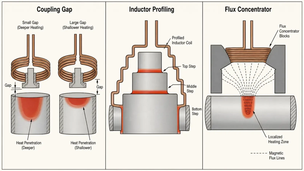
There are three primary design levers that control where heat goes and how deep it penetrates: coupling gap, inductor profiling, and flux concentrators. Each gives the engineer a different level of control. Used together, they can produce a hardening pattern that is accurate, stable, and well-matched to the part design.
1. Coupling Gap — The First Lever for Heating Intensity
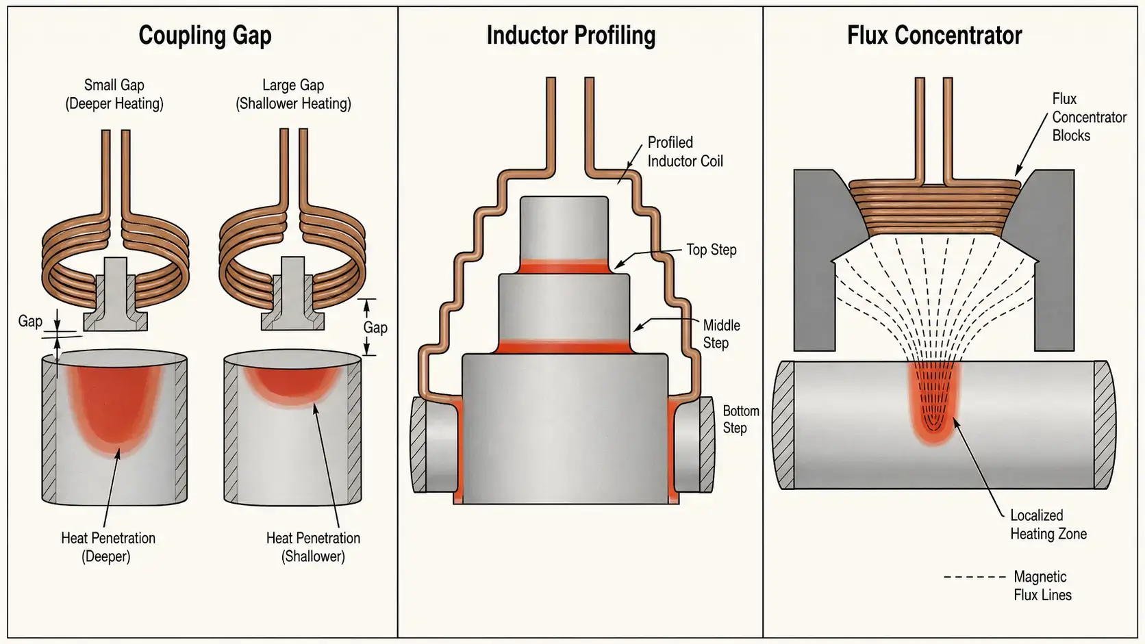
The coupling gap is the distance between the inductor and the workpiece surface. It is the simplest and fastest way to adjust local heating intensity in selective induction hardening. The physics is direct: electromagnetic coupling strength falls off rapidly with distance. A smaller gap means stronger coupling and more induced current in the part. A larger gap means weaker coupling and less heat.
In practice, coupling gap control follows a predictable pattern:
— 1.5–3 mm gap: Strong coupling, deeper case depth (3–5 mm typical), faster heating. Used for zones that need full hardening depth.
— 3–6 mm gap: Moderate coupling, shallower case (1–3 mm). Used for transition zones or areas that need only surface treatment.
— 6–10 mm gap: Weak coupling, minimal or no hardening. Used to skip zones that must stay soft.
During process development, coupling gap adjustment is often the first tuning step. It requires no tooling changes—just repositioning the coil relative to the part. However, gap control alone has a practical limit: on complex geometries with shoulders, radii, or sudden cross-section changes, a uniform gap cannot produce a sharply defined heating zone. That is where profiling takes over.
2. Inductor Profiling — Matching the Coil to the Part
A straight cylindrical inductor does not heat a part evenly from end to end. The center of the coil produces stronger heating than the edges because of electromagnetic edge effects—the magnetic field is less constrained at the coil ends, so coupling efficiency drops there. On a simple shaft, this produces a barrel-shaped heating profile: deeper hardening in the middle, shallower at the ends. That is rarely what the part drawing calls for.
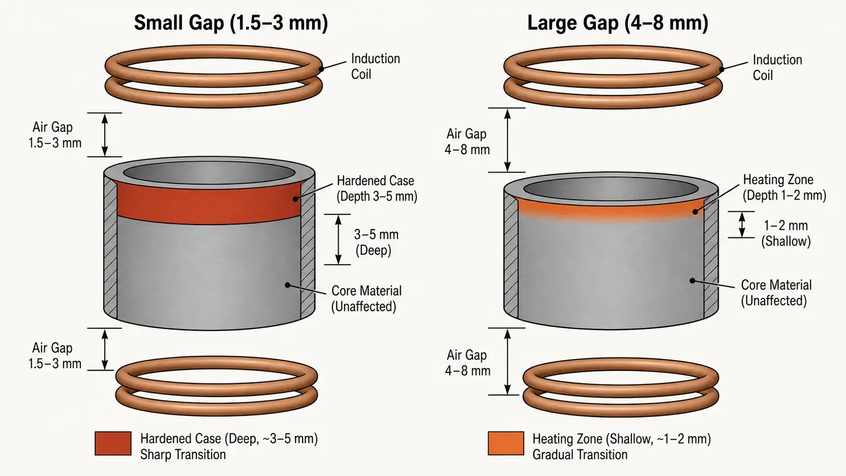
An inductor profile is a deliberate shaping of the coil to follow the workpiece contour. The profile can tighten the gap at the ends to compensate for edge losses, open the gap over areas that need less heat, or contour around features like flanges and steps. The result is a heating pattern that matches the part geometry rather than fighting it.
— Reduces center overheating: By adjusting the coil profile, you prevent the barrel-shaped pattern and produce flatter case depth from end to end.
— Improves edge heating: Tighter coupling at the coil ends compensates for the natural drop-off in field strength.
— Matches hardened zone to part shape: For stepped shafts, shouldered axles, and parts with multiple diameters, profiling keeps the case depth consistent across geometry changes.
— Controls final hardening depth more consistently: A well-profiled coil reduces the need for power trimming during production.
Profiling is especially valuable for parts with shoulders, steps, transitions, or multiple surfaces that require different hardening levels. Applications like internal bore hardening depend heavily on profiling, since the coil must conform to a confined ID geometry while producing a uniform case around the bore circumference.
3. Flux Concentrators — Precision When Gap and Profile Aren’t Enough
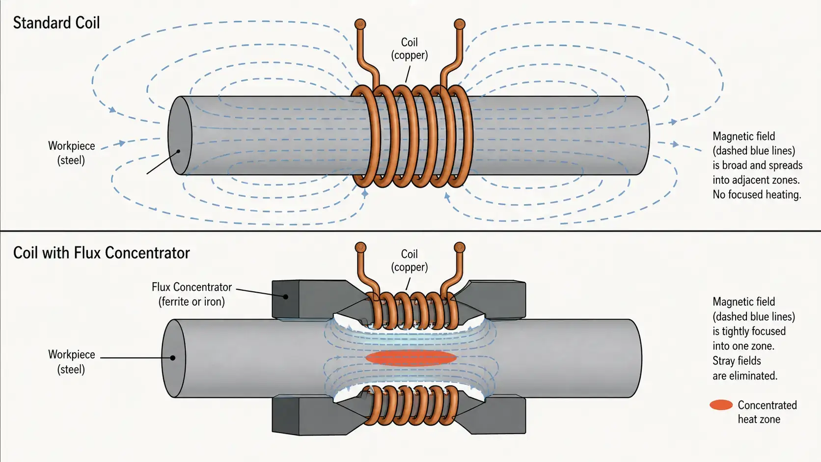
If coupling gap is the coarse adjustment and profiling is the shape adjustment, flux concentrators are the fine-tuning tool. A flux concentrator is a magnetic material placed on or near the inductor that redirects the magnetic field—essentially blocking it from areas you want to protect and focusing it into areas you want to heat. It does not change the coil geometry or the part position. It changes where the magnetic flux actually goes.
With a properly designed flux concentrator, the engineer can control three things simultaneously: where the heat is delivered, how intense it is in each zone, and how uniform the temperature becomes across the target area. This makes flux concentrators indispensable when a part needs sharply different hardening levels along its length—for example, a shaft with a hardened bearing journal next to a soft spline section.
The material choice for flux concentrators depends on the operating frequency range:
— Laminated silicon steel: For low frequencies below 10 kHz. High magnetic permeability, low cost, but eddy-current losses increase rapidly above 10 kHz.
— Ferrite: For medium frequencies from 10 kHz to roughly 100 kHz. Low electrical conductivity keeps eddy-current losses manageable, good permeability at mid-range frequencies.
— Soft magnetic composites (SMC): For higher frequencies above 100 kHz. Pressed powder materials with distributed air gaps, very low eddy-current losses, can be machined to complex shapes.
In many selective induction hardening applications, flux concentrators provide finer spatial control than gap adjustment or profiling alone can achieve. The trade-off is that they add design complexity and material cost—but for parts where the hardening pattern specification is tight, they are often the only practical solution.
4. How to Combine All Three Methods
In production hardening, the best results rarely come from using just one method. Each lever has a different strength, and they work together in a logical hierarchy:
| Method | Control Precision | Cost Impact | Best Used For |
|---|---|---|---|
| Coupling Gap | Low–Medium | Minimal | Broad intensity adjustment, process tuning |
| Inductor Profiling | Medium–High | Moderate | Matching part contours, reducing edge effects |
| Flux Concentrators | High | Higher | Pinpoint zone control, complex field shaping |
A practical design sequence looks like this: start with the coupling gap to set the broad heating intensity across the part. Then use inductor profiling to match the coil shape to the workpiece geometry—compensating for edge effects, following contours, opening up over areas that should stay cool. Finally, add flux concentrators for fine-tuning: directing stray flux away from protected zones and concentrating it into the target area.
When these three tools are deployed together, the inductor delivers heat exactly where it is needed—and keeps it away from areas that must remain unhardened. The process becomes more stable because each method addresses a different source of variation: gap handles coupling strength, profiling handles geometry matching, and flux concentrators handle field shaping.
5. Scanning Hardening vs Single-Shot Hardening
The choice between scanning and single-shot affects how much of your zone control must be built into the coil versus how much can be handled by the process parameters. In scanning hardening, the inductor moves along the part during heating. You can vary power, scan speed, and dwell time as the coil passes through different zones. This dynamic control makes it easier to produce varying case depths along a single part without complex coil geometry.
In single-shot hardening, the inductor and workpiece remain stationary. The entire heating pattern is determined before the power comes on—by the coil geometry, the coupling gap at each point, and any flux concentrators installed. There is no real-time adjustment during the heat cycle. For this reason, single-shot applications depend more heavily on coil design quality from the start. The three design levers described above—gap, profiling, flux concentrators—are not optional in single-shot; they are the primary means of control.
If your application requires precise local hardening and your production volume justifies single-shot tooling, the inductor should be designed with the same level of care as the power supply and process settings. For a deeper comparison of scanning and single-shot systems, see our guide on how to select an induction hardening system.
6. 5 Practical Design Tips for Better Zone Control
— 1. Do not rely on power alone. Power level controls how much total energy goes into the part, but it cannot fix a poorly designed inductor. If the magnetic field is not shaped correctly, increasing power often makes the problem worse by overheating the areas that already heat fastest.
— 2. Check the part geometry early. The shape of the workpiece—cross-section changes, radii, shoulders, keyways—has a major impact on heating uniformity. Features that concentrate or scatter the magnetic field should be identified before coil design begins, not discovered during process trials.
— 3. Test gap changes systematically. A 1 mm change in coupling gap can produce a measurable difference in case depth. During setup, vary the gap in controlled increments and record the result. This data becomes the basis for production tolerances.
— 4. Use profiling to reduce edge effects first. Before adding flux concentrators, optimize the coil profile. Profiling is usually the fastest way to improve end-to-end uniformity, and it avoids the additional material cost and assembly complexity that concentrators bring.
— 5. Add flux concentrators when you need tighter control. If the heating pattern is still too broad or uneven after optimizing gap and profile, flux concentrators can sharpen it. They are particularly effective when you need a hard transition boundary between a hardened zone and an adjacent soft area—for example, within a few millimeters of a snap-ring groove or oil hole.
The common thread across all five tips: inductor design drives zone control. The power supply provides the energy, but the coil determines where that energy actually goes. For more on what can go wrong when zone control is inadequate, our guide to common induction hardening defects covers the symptoms—uneven case depth, soft spots, and pattern shift—that often trace back to inductor design.
Key Takeaway
Selective induction hardening is about putting heat in the right place and controlling how deep that heat goes—nothing more, nothing less. For localized hardening applications, the three most useful design levers are coupling gap for broad intensity control, inductor profiling for geometry matching, and flux concentrators for precision field shaping. Used together in sequence—gap first, then profile, then concentrators—they allow you to create a heating pattern that is accurate, stable, and well-matched to the part drawing. If you need to harden only specific zones of a workpiece, design the inductor as carefully as you select the power supply and process settings.
FAQ
Q: What is selective induction hardening?
A: Selective induction hardening means heating and quenching only specific zones of a part—such as bearing journals, seal surfaces, or gear teeth—while leaving adjacent areas unhardened. This preserves toughness and ductility in non-critical areas while achieving the required hardness in wear or fatigue-prone zones.
Q: What is the easiest way to control hardening depth?
A: The coupling gap is the easiest starting point. A smaller gap (1.5–3 mm) increases electromagnetic coupling and produces deeper case depth. A larger gap (3–10 mm) weakens coupling and produces shallower or no hardening. Gap adjustment requires no tooling changes and can be tested quickly during process development.
Q: What materials are used for flux concentrators?
A: Three material families are commonly used: laminated silicon steel for low frequencies (below 10 kHz), ferrite for medium frequencies (10–100 kHz), and soft magnetic composites (SMC) for high frequencies (above 100 kHz). The choice depends on operating frequency, required precision, and part geometry.
Q: Is scanning hardening easier to control than single-shot hardening?
A: Generally yes. Scanning hardening allows you to adjust power and scan speed dynamically as the coil moves across different zones. Single-shot hardening produces the entire heating pattern in one stationary cycle, so coil design—gap, profiling, and flux concentrators—determines the result. Single-shot demands more upfront engineering, but it can achieve higher throughput for high-volume production.
Need a Custom Coil for Selective Hardening?
Tell us about your part geometry, target zones, case depth requirements, and production volume. We’ll help you design an inductor that delivers heat exactly where you need it.


