
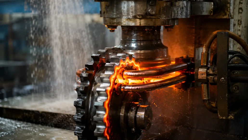
Solving 2 Critical Gear Induction Hardening Defects: Non-Martensitic Structure & Distortion
Gear induction hardening often encounters two critical defects that can scrap a batch before anyone catches them: unexpectedly low surface hardness caused by non-martensitic structures, and post-quench distortion that pushes run-out beyond blueprint tolerance. This article walks through the root causes and the most practical fixes — drawn from production experience with C45E sprockets and 45# ring gears.
📋 Table of Contents
1. Engine Sprockets: The Non-Martensitic Structure Problem
The Setup
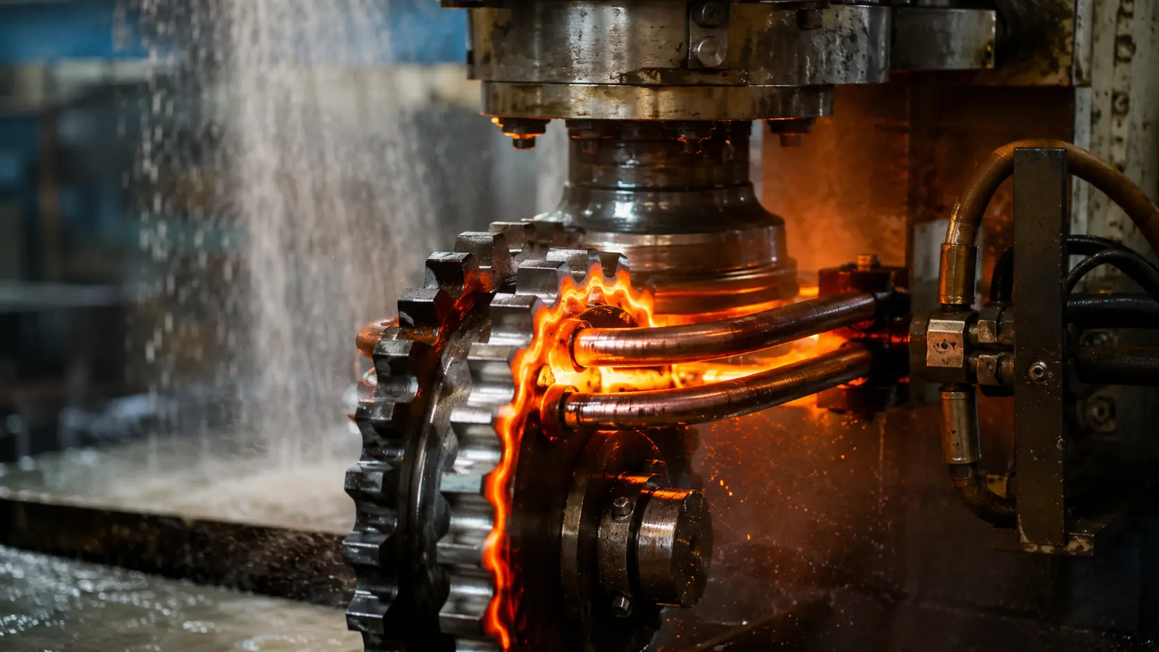
Material: C45E steel, 6 mm tooth thickness. Surface hardness target: ≥58 HRC. The gear induction hardening setup uses a 100 kW / 80 kHz high-frequency power supply, single-turn copper coil, and rotating spindle feed.
The Defect
Fine-blanking leaves a cold-worked deformed layer at the tooth tips. During rapid induction heating, this deformed microstructure resists austenitization.
The result is a thin band of non-martensitic structure at the very surface where hardness matters most, capping the achievable hardness well below specification. Metallography confirms ferrite islands in a martensitic matrix right at the tooth flank (Reference: ASM Handbook Vol. 4C — Induction Hardening).
The Fix
The most practical path is a 100 °C low-temperature temper immediately after quenching. This preserves peak as-quenched hardness while relieving micro-stresses that make the non-martensitic layer brittle. For a broader comparison of hardening process strategies across different gear types, see our guide on single-shot vs. tooth-by-tooth induction hardening for drive wheels.
Equally critical is tightening the heating cycle: run at full power from the first millisecond, and control cycle time in 0.5-second increments. Once both measures are in place, batch-to-batch hardness scatter narrows dramatically.
2. Flywheel Ring Gears: Distortion Control in Gear Induction Hardening
The Setup
Material: 45# carbon steel. Typical ring gear diameter: 300–500 mm. The blueprint demands a post-quench run-out of ≤0.15 mm — a tolerance nearly impossible to hold by tuning power parameters alone.
The Defect
During immersion quenching, the ring cools unevenly — the bottom face in contact with the fixture cools slower than the exposed top face. This asymmetric cooling creates a thermal stress gradient that warps the ring into an oval, with run-out values easily exceeding 0.3 mm.
The Fix
This requires a two-pronged approach — fixture + post-processing:
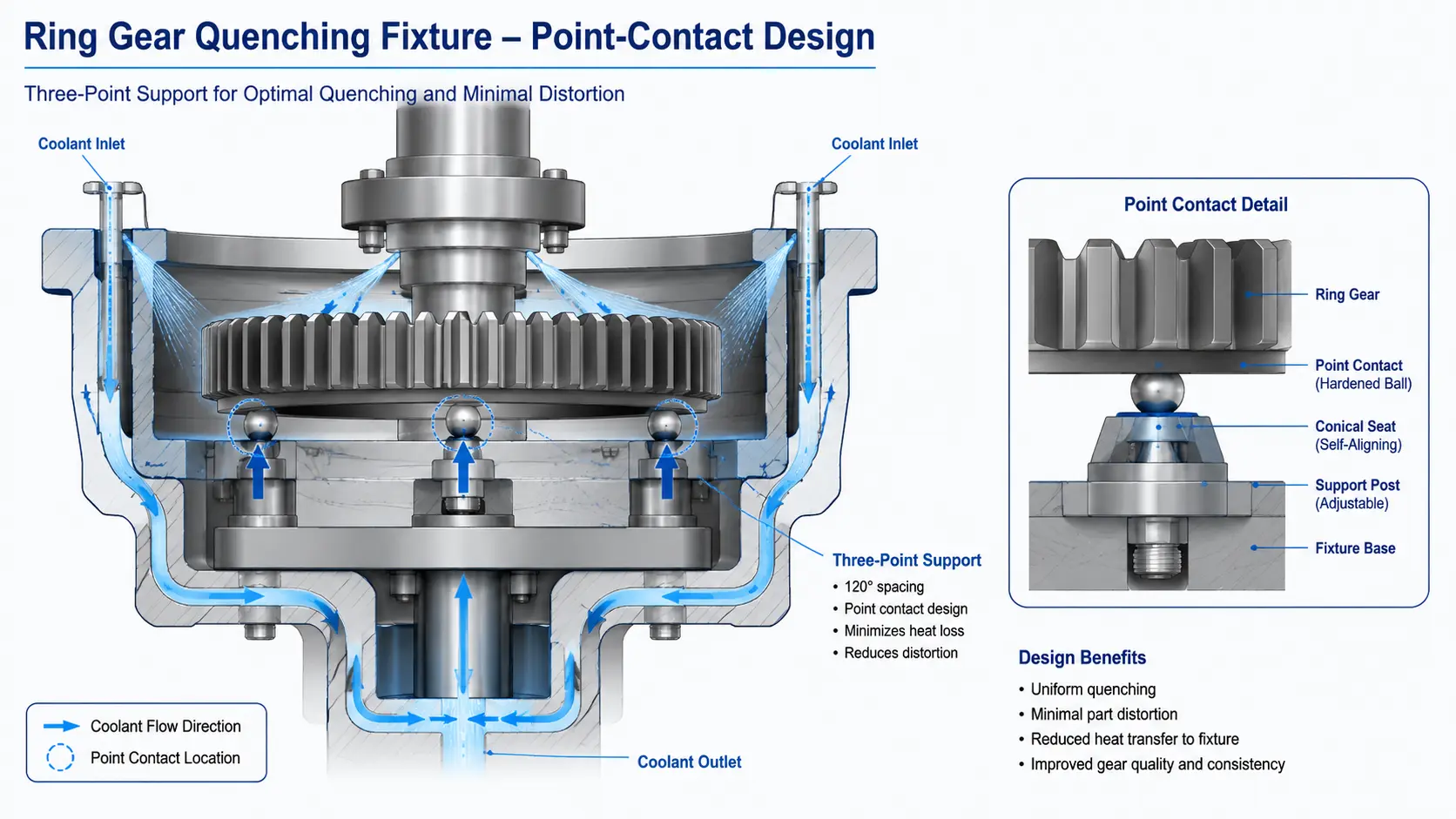
1. Point-contact quenching fixture. Replace full-surface-contact fixturing with a three-point contact design. By minimizing the contact area, coolant circulates uniformly around the entire part, eliminating the differential cooling that causes warpage.
The fixture material must have low magnetic permeability — stainless steel or specific copper alloys — to avoid parasitic induction heating at the contact points (See also: Gear Solutions — Induction Gear Hardening Part 2).
2. Inline CNC straightening. Even with an optimized fixture, some distortion is inevitable in thin-walled rings. Integrating a CNC straightening machine immediately downstream of the quench station measures run-out on every part and applies controlled mechanical correction to bring it back within the 0.15 mm envelope.
Key Takeaway
A stable gear induction hardening process depends as much on what happens before the coil heats the part (microstructure from prior forming) as on what happens after (fixture design and straightening).
For sprockets, the lever is metallurgical — recognize and mitigate the fine-blanking deformation layer with precise tempering. For ring gears, the lever is mechanical — invest in point-contact fixturing and inline straightening. In both cases, the fix is not a more expensive power supply; it’s smarter process engineering around it. Related reading: Single-Shot vs. Tooth-by-Tooth — How to Choose the Right Induction Hardening Process for Drive Wheels
FAQ: Common Questions About Gear Induction Hardening
Q1: Why does fine-blanking cause non-martensitic structure in gear induction hardening?
Fine-blanking introduces intense cold plastic deformation at the tooth tips. This deformed microstructure has a lower austenitization temperature than the base material. During rapid induction heating (typically under 2 seconds), the heat input is too brief to fully homogenize the austenite in this deformed zone.
The result is ferrite islands trapped in the martensitic matrix after quenching — the “non-martensitic structure” — and because ferrite is orders of magnitude softer than martensite, surface hardness drops significantly right where wear resistance is most needed.
Q2: Why use low-temperature tempering (100 °C) instead of a higher temper?
Standard tempering for induction-hardened gears typically runs at 150–200 °C, but in this case that would sacrifice too much surface hardness.
The 100 °C low-temperature temper is a deliberate compromise: it preserves the peak as-quenched hardness while relieving enough residual stress to prevent the non-martensitic layer from cracking under service loading — a stress-relief step rather than a full temper.
Q3: What makes point-contact fixturing better than full-surface support?
When a ring gear sits flat against a full-surface fixture during quenching, the bottom face cools significantly slower than the exposed top face — the fixture acts as a thermal insulator. This asymmetric cooling warps the ring into an oval, easily exceeding 0.3 mm run-out.
A three-point contact fixture eliminates this problem by letting quenching liquid circulate uniformly around both faces. The trade-off: point contacts concentrate mechanical stress, so fixture material selection — low magnetic permeability, high hot strength — becomes critical.
Q4: Can I solve distortion in gear induction hardening by adjusting power and frequency alone?
No. For thin-walled ring gears (diameter-to-thickness ratio above 20:1), thermal-only solutions hit a physical limit: the temperature gradient required for through-hardening inherently creates uneven thermal contraction during quenching.
The only reliable approach is point-contact fixturing plus inline CNC straightening as a mechanical safety net. Power parameter tuning alone will never consistently meet a ≤0.15 mm run-out specification.
Contact Us for a Free Process Evaluation
If you are dealing with hardness scatter or post-quench distortion in your gear induction hardening line, contact our engineering team for a free process evaluation.
Send us your workpiece drawing, material grade, and current process parameters, and we will deliver a preliminary diagnosis and optimization proposal within 48 hours — covering power supply configuration, coil design, fixturing recommendations, and where applicable, inline straightening integration.
Take the next step: share your part print and production requirements. Our application engineers will analyze your process bottlenecks at no cost and recommend targeted fixes — whether that means low-temperature tempering, point-contact fixturing, or an inline CNC straightening station matched to your throughput.


