
How Frequency Affects Induction Heating: 5 Critical Effects on Depth, Pattern & Efficiency
Pick the wrong frequency for an induction heating job, and the part is scrap before the quench even starts. How frequency affects induction heating is not a theoretical detail — it is the first decision that governs every result that follows: case depth, heating pattern, cycle time, and power requirement. Get it right, and you dial in the process quickly. The physics behind this is straightforward — the skin effect — and understanding it lets you make predictable choices instead of guessing at parameters. This article breaks down exactly how frequency controls heating behavior and how to match it to your application.
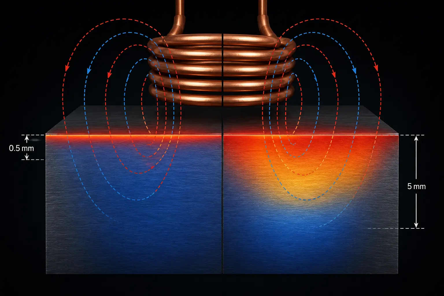
Table of Contents
1. The Skin Effect: Why Frequency Controls Heating Depth
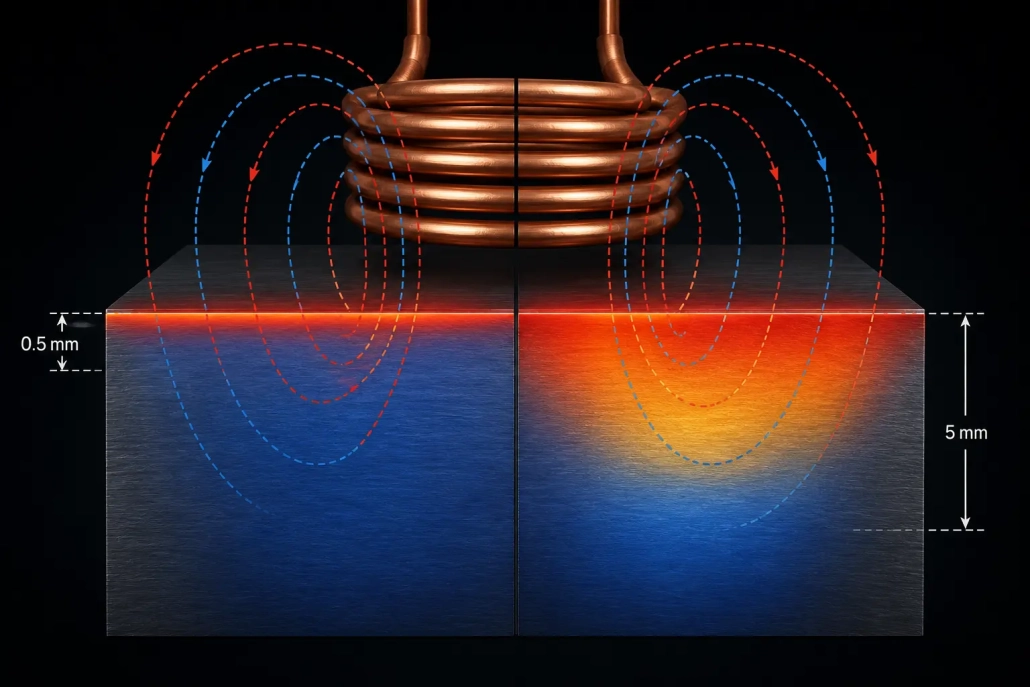
When alternating current flows through a conductor — whether the copper coil or the workpiece itself — the current does not distribute evenly through the cross-section. It crowds toward the surface. This is the skin effect, and it is the physical mechanism that makes frequency the dominant control knob for heating depth in induction heating.
The higher the frequency, the more aggressively current is pushed to the surface — and the shallower the heated layer becomes. At 400 kHz, the current-carrying depth in steel at 800°C is roughly 0.5 millimeters. At 3 kHz, that same depth expands to approximately 5 millimeters — a factor of 10 difference from frequency alone.
This relationship is captured by the reference depth formula (δ = √(ρ/πfμ)), but the engineering takeaway is simpler: frequency and depth are inversely related. Double the frequency, and the heated depth shrinks by roughly 40%. Halve it, and depth increases by the same proportion. This is why how induction heating works at a fundamental level is inseparable from frequency — the skin effect is not a side detail; it is the core mechanism.
For magnetic steels below the Curie point (≈770°C), the effect is even stronger because magnetic permeability (μ) amplifies current crowding. Once the steel passes the Curie temperature and becomes non-magnetic, the current penetrates deeper — which is why the heating pattern can shift mid-cycle on longer heat times.
2. Frequency Ranges and Their Practical Effects
Induction heating equipment is grouped into four frequency bands. Each band produces a characteristic heating depth in steel and maps to specific industrial applications. The full classification system is covered in our guide to induction heating frequency classification — here we focus on what each range actually does to the workpiece.
Low Frequency (50 Hz – 1 kHz): Deep Penetration
At these frequencies, current penetrates 5 to 10+ millimeters into steel. Heating is deep and broad — too broad for most surface hardening applications. This range is used for through-heating of large billets and bars prior to forging, and for power-frequency induction furnaces where the goal is melting or heating the entire cross-section. If you use low frequency for surface hardening, you will overheat the core before the surface reaches temperature.
Medium Frequency (1–10 kHz): The Workhorse for Case Hardening
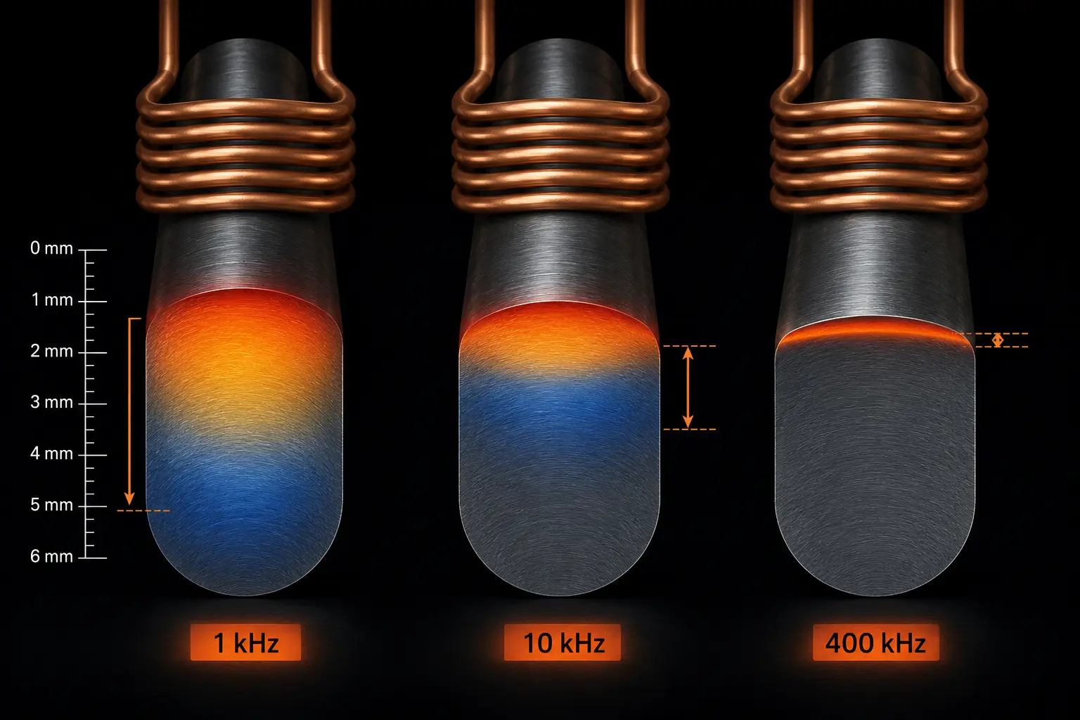
Medium frequency produces 2 to 5 millimeters of heated depth in steel. This is the sweet spot for most gear hardening, shaft hardening, and bearing ring hardening applications where case depths of 1.5–4 mm are specified. Parts with moderate cross-sections — gears over module 4, shafts above 30 mm diameter, bearing rings — respond predictably in this range. The penetration is deep enough to heat through the specified case but shallow enough to leave the core cold for self-quenching support.
Super-Audio Frequency (10–40 kHz): Shallow to Medium Depth
Super-audio frequency concentrates heating in the 0.8 to 2 millimeter range. It is the default choice for cam lobes, small gears, thin-walled bearing rings, and shift forks — parts where keeping the hardened case tight to the surface is critical. This range also dominates automotive component hardening because it balances reasonable penetration with tight zone control.
High Frequency (100–400 kHz): Surface-Only Heating
High frequency confines heating to 0.3 to 0.8 millimeters — essentially the skin of the part. It is used for small-diameter pins, thin cutting edges, precision instrument parts, and small module gears where case depth is specified under 1 mm. What is high frequency induction heating best at? Delivering energy so tightly to the surface that the core stays completely cold — enabling very high surface hardness with no distortion risk. The trade-off: if your case depth spec is over 1 mm, high frequency alone will not get there — you will need to increase cycle time and rely on thermal conduction, which sacrifices the precision that high frequency provides.
3. How to Match Frequency to Your Application
The starting rule is straightforward: the required case depth should be at least 2 to 3 times the reference depth at the chosen frequency. If your case depth specification is 2 mm, you need a frequency that gives a reference depth of roughly 0.7–1 mm — which puts you in the 3–10 kHz range (medium frequency).
But frequency does not work in isolation. It is locked together with power density and heating time. Higher power at the same frequency heats the surface faster, leaving less time for heat to conduct inward — producing a sharper case-to-core transition. Lower power with a longer cycle lets conduction carry heat deeper, softening the transition but increasing total energy input and potentially overheating the surface.
This interdependence is why induction heating power selection must happen alongside frequency selection, not after it. A frequency that is theoretically correct will still produce scrap if paired with the wrong power density. The two parameters are a single decision.
Part geometry also constrains frequency choice. For shaft induction hardening, the diameter-to-frequency relationship dictates how evenly the circumference heats — too high a frequency on a large-diameter shaft produces uneven heating because the current path around the part circumference becomes electrically long relative to the skin depth. For gear hardening, frequency also controls whether the tooth tip and root both reach temperature: too high, and the tip overheats before the root gets hot; too low, and the root softens while waiting for the tip.
4. Signs You Chose the Wrong Frequency
Wrong-frequency problems are not subtle. They show up as one of three patterns in production.
Frequency too high: The surface reaches temperature quickly and looks correct, but the case depth is too shallow. You respond by increasing cycle time to let heat conduct deeper, but now cycle time is uncompetitive and the surface may overheat before the target depth hits temperature. The hardened case also has a sharp, abrupt transition to the core — a metallurgical stress riser that can cause spalling under load.
Frequency too low: Heat penetrates too deep — into the core of the part. The core heats up, reducing its ability to self-quench the surface during cooling. You end up with a deeper case than specified, a softer core, and potentially through-hardening on thin sections. Distortion increases because the entire part is thermally stressed rather than just the surface. These problems overlap with common gear induction hardening defects where incorrect frequency is often the hidden root cause behind uneven hardness patterns.
Frequency mismatched to part geometry: This is the hardest to diagnose because it produces uneven heating — some zones are correct, others are under- or over-heated. On gears, the tooth tip is hot while the root is cold (frequency too high). On large shafts, the heating pattern breaks into nodes — hot and cold bands alternating around the circumference. The fix is not more power or more time; it is a different frequency.
Frequency problems in shaft induction hardening are particularly common because shaft diameters vary widely and the diameter-to-frequency relationship is unforgiving — a frequency that works for a 40 mm shaft will produce uneven heating on an 80 mm shaft of the same material.
🔑 Key Takeaway
Frequency is the single most important parameter in induction heating process design because it directly controls how deep the current penetrates — and therefore where the heat is generated. The skin effect makes this relationship predictable: higher frequency = shallower heating, lower frequency = deeper heating.
Choose frequency first, match power to it second, and verify the result against your case depth specification. A frequency that is wrong by one range band cannot be compensated for by adjusting power, time, or inductor geometry — it is a fundamental mismatch that will show up as scrap, rework, or field failure.
FAQ
How does frequency affect induction heating depth?
Frequency and heating depth are inversely related through the skin effect. Higher frequency pushes current closer to the surface, producing a shallower heated layer. At 400 kHz in hot steel, current is confined to roughly 0.5 mm from the surface. At 3 kHz, it penetrates approximately 5 mm — ten times deeper. The relationship follows a square-root law: doubling the frequency reduces penetration depth by about 40%.
What frequency should I use for induction hardening?
Choose frequency so your target case depth is 2–3 times the reference penetration depth at that frequency. For case depths of 1.5–4 mm (gears, shafts, bearings), medium frequency (1–10 kHz) is typical. For 0.8–2 mm (cam lobes, small gears), super-audio frequency (10–40 kHz) works best. For case depths under 1 mm, high frequency (100–400 kHz) is appropriate. For through-heating or very deep cases over 5 mm, low frequency (50 Hz–1 kHz) is required.
What happens if I choose the wrong frequency?
Too high a frequency produces a case that is too shallow with a sharp transition to the core — a spalling risk under load. Too low a frequency heats too deep, potentially softening the core and causing distortion. A frequency mismatched to part geometry produces uneven heating (hot and cold bands around the circumference, or tooth tip hot while root is cold on gears). None of these can be fully corrected by adjusting power or time alone — the frequency itself must change.
Need Help Matching Frequency to Your Application?
Our engineering team can review your part geometry, case depth requirements, and production targets to recommend the right frequency and power combination. Fast technical assessment with no obligation.


