
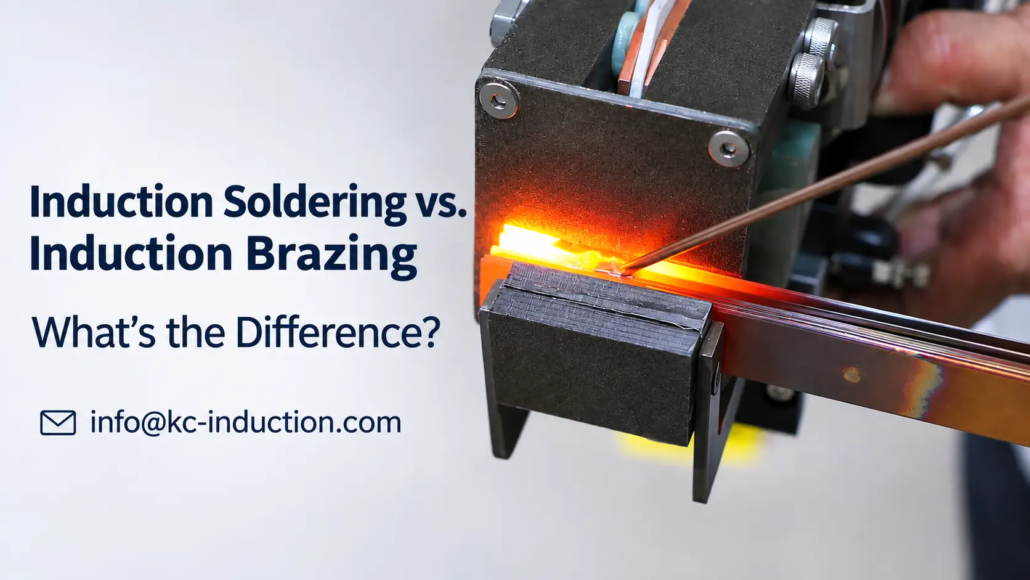
Induction Soldering vs. Induction Brazing: What’s the Difference?
How Filler-Metal Temperature, Joint Requirements and Induction Heating Affect Process Selection
Induction soldering and induction brazing both use electromagnetic induction to heat metal components for joining. In either process, the filler metal melts, wets the adjoining surfaces and solidifies to form a joint without intentionally melting the base materials.
The two processes differ in filler-metal temperature, typical joint requirements and the thermal conditions needed for successful joining. These differences affect which method is appropriate for a particular assembly.
Quick Answer: The main difference between induction soldering and induction brazing is the liquidus temperature of the filler metal. Under AWS A3.0M/A3.0:2025 terminology, soldering uses a filler metal with a liquidus at or below 450°C (approximately 840°F), while brazing uses a filler with a liquidus above 450°C but below the solidus temperature of the base materials. Both processes can use induction heating. Soldering is often selected for lower-temperature joining, including suitable electrical connections, while brazing provides filler-metal options for joints requiring greater mechanical strength or higher service-temperature capability.
2. How Does Induction Heating Differ Between Soldering and Brazing?
3. How Do Filler Metals, Wetting and Joint Design Affect the Result?
4. When Should Induction Soldering or Induction Brazing Be Selected?
5. How Can the Selected Induction Joining Process Be Verified?
1. What Is the Difference Between Induction Soldering and Induction Brazing?
The classification depends on the filler metal, not the induction power supply or heating coil.
The American Welding Society (AWS) distinguishes soldering from brazing using the liquidus temperature of the filler metal. Liquidus is the temperature above which an alloy is completely liquid.
This is more precise than using a general melting point, because many filler alloys melt over a temperature range.
| Comparison | Induction Soldering | Induction Brazing |
|---|---|---|
| Filler-metal liquidus | At or below 450°C | Above 450°C, below the base-metal solidus |
| Heating method | Electromagnetic induction | Electromagnetic induction |
| Base-metal melting | Not intended | Not intended |
| Typical filler systems | Tin-based and other low-temperature solder alloys | Silver-, copper-, aluminum- or nickel-based brazing alloys |
| Joining mechanism | Filler wetting, capillary action and solidification | Filler wetting, capillary action and solidification |
| Thermal exposure | Generally lower | Generally higher |
| Typical applications | Electrical connections, connectors and selected low-temperature metal joints | Tubing, heat exchangers, cutting tools and mechanically demanding assemblies |
| Main selection concerns | Electrical properties, thermal sensitivity and service conditions | Joint strength, service temperature, material compatibility and joint design |
The 450°C boundary is a filler-metal classification threshold. It is not a universal workpiece temperature or recommended induction-heating setpoint.
Actual joining temperatures must be sufficient for the chosen filler to wet and flow across the mating surfaces. They depend on its melting range, the base materials and the joint geometry.
Why is this distinction important?
Consider a copper tube connected to a brass fitting.
The assembly might be joined using either a suitable solder alloy or a brazing filler, depending on the operating conditions and applicable specifications.
The heat source could be induction in both cases. Changing the filler metal and its required joining conditions, however, changes the process classification and may change the joint’s performance.
How are soldering and brazing different from welding?
Soldering and brazing form joints using molten filler metal while the base materials remain solid.
Fusion welding, by contrast, involves melting the base material at the joint. Other welding methods can produce solid-state joints without melting the base material.
For example, certain high-frequency induction welding processes heat mating edges that are subsequently forced together to form a weld.
Therefore, induction welding, induction soldering and induction brazing should not be used interchangeably.
The terminology should describe the actual joining mechanism.
The American Welding Society’s brazing and soldering information and its AWS A3.0M/A3.0:2025 terminology standard provide the relevant definitions.
2. How Does Induction Heating Differ Between Soldering and Brazing?
The electromagnetic heating principle is the same in both processes.
Alternating current in an induction coil produces a changing magnetic field. This induces electrical currents in conductive workpieces, generating heat through electrical resistance.
For soldering and brazing, the induction system is arranged to deliver heat to the components around the joint.
The filler metal may receive much of its heat through conduction from the surrounding metal surfaces rather than through direct induction heating.
What changes between the processes is the required thermal cycle and the way that heat must be controlled.
Induction soldering: controlling lower-temperature joining
Soldering generally requires lower joining temperatures than brazing.
This can be useful for assemblies containing temperature-sensitive components, coatings, insulating materials or nearby mechanical features that should not experience unnecessary heating.
However, lower filler-metal temperature does not guarantee that surrounding components will remain cool.
Metal conductors and housings can transfer heat away from the intended joint. If the induction cycle is too long, nearby components may still reach damaging temperatures.
The process must heat the actual joining surfaces sufficiently for solder wetting while limiting thermal exposure elsewhere.
A solder alloy melting at the joint does not, by itself, prove that both mating surfaces have reached suitable joining conditions.
Induction brazing: heating the joint without excessive thermal exposure
Brazing generally requires higher joining temperatures.
The additional thermal exposure can increase the importance of oxidation control, thermal expansion, component alignment and the response of nearby materials.
For example, when brazing a thick brass fitting to a thin copper tube, the two components may heat differently because of their geometry, thermal mass and heat conduction.
If one component becomes sufficiently hot while the other remains too cool, the filler may not wet the entire joint.
Excessive heating can also produce unnecessary oxidation or disturb the assembly.
The objective is to establish suitable conditions across the mating surfaces, rather than simply heating the most accessible portion of the joint.
What does the induction system need to control?
For either joining method, the relevant factors include:
— Coil coupling and position relative to the joint.
— Heating response of each base material.
— Component dimensions and thermal mass.
— Heat conduction into adjacent regions.
— Time available for filler wetting and flow.
— Temperature limits of nearby materials.
These factors determine whether the heat reaches the required surfaces in a suitable and repeatable manner.
A system capable of reaching brazing temperatures may also be suitable for soldering, but that capability alone does not establish satisfactory low-temperature process control.
Similarly, equipment designed for a small soldered connector may not have the heating capacity or appropriate coil arrangement for a larger brazed assembly.
The heating arrangement must be developed for the specific joint.
3. How Do Filler Metals, Wetting and Joint Design Affect the Result?
Filler-metal selection is central to both processes.
Its composition determines the melting range and influences wettability, joint properties, corrosion compatibility and acceptable service conditions.
Filler-metal composition and compatibility
Tin-based alloys are widely used for soldering applications, particularly electrical connections and certain lower-temperature metal joints.
Brazing fillers may contain silver, copper, aluminum, nickel or other alloying elements, depending on the base materials and service requirements.
The presence of silver does not necessarily mean a joining process is brazing.
Some silver-containing alloys are soldering fillers, while others have liquidus temperatures above 450°C and are classified as brazing fillers.
This distinction is especially relevant to the older term silver soldering, which is sometimes used for processes that meet the modern definition of brazing.
Filler selection must consider more than melting temperature. A filler that melts within the available temperature range may still be unsuitable because of poor wettability, inadequate mechanical properties or incompatibility with the service environment.
Surface preparation and wetting
Both soldering and brazing require molten filler metal to wet the mating surfaces.
Oxides, oils and other contamination can interfere with wetting and prevent satisfactory joint formation.
Suitable fluxes may be used to control surface oxides. Certain joining applications instead use controlled atmospheres or other protective methods.
The appropriate method depends on the materials, filler alloy and production conditions.
Induction heating supplies the energy needed for joining, but it does not automatically eliminate surface contamination or guarantee filler wetting.
Capillary action and joint clearance
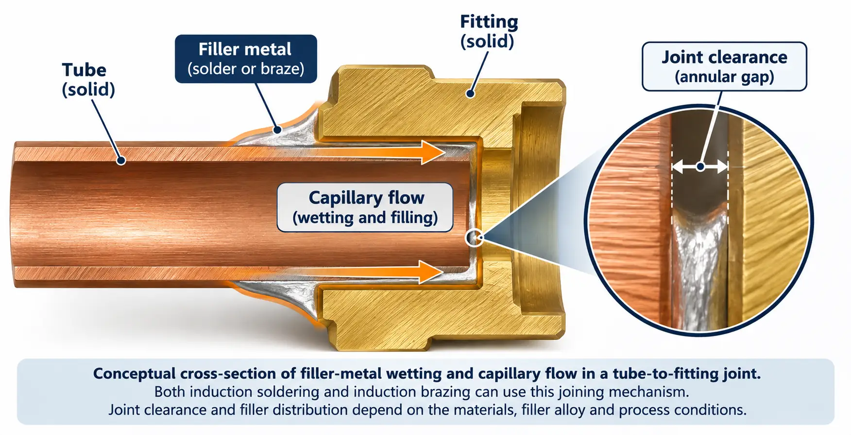
In many soldered and brazed assemblies, molten filler is drawn into the space between closely fitted surfaces through capillary action.
The joint clearance influences how effectively the filler can enter and fill that space.
If the clearance is too small, filler penetration may be restricted, depending on surface condition, flux behavior and the filler system.
If the clearance is excessive, capillary action may be insufficient for complete joint filling or the resulting joint may not have the required properties.
An appropriate clearance must therefore be established for the selected materials and filler alloy.
The clearance at joining temperature may differ from the assembly clearance.
This is particularly important when joining dissimilar metals.
Different materials expand by different amounts during heating. As a result, a joint assembled with a suitable clearance at room temperature may have a smaller or larger clearance when the filler metal becomes liquid.
For example, a copper tube inside a steel fitting may expand differently from the surrounding fitting during brazing. Depending on the geometry and materials, the clearance can become narrower during heating.
The final joint design should account for these effects rather than relying only on the room-temperature dimensions.
The TWI guidance on brazing explains the importance of joint geometry and capillary flow.
Is brazing always stronger than soldering?
Brazing generally offers filler-metal systems suitable for greater mechanical demands and higher service temperatures.
That does not mean every brazed joint is stronger than every soldered joint.
Actual performance depends on the filler alloy, base materials, joint geometry, loading conditions and quality of the completed joint.
A properly designed soldered electrical connection may meet all relevant requirements. A poorly designed or incompletely filled brazed joint may fail despite being produced at a higher temperature.
The correct comparison is between joints that satisfy the same defined service requirements.
4. When Should Induction Soldering or Induction Brazing Be Selected?
The choice depends on the intended use of the joint, especially its mechanical, electrical and thermal requirements.
Choose induction soldering when lower thermal exposure is important
Induction soldering may be suitable for selected electrical connectors, terminals, conductor assemblies and other metallic joints that can meet their service requirements with a lower-temperature filler.
Relevant considerations include electrical continuity, contact resistance, component temperature limits and the durability of the finished connection.
Metal connections used in antenna phase-shifter assemblies are one possible application of induction soldering.
Such applications still require careful evaluation of the actual conductive components and nearby temperature-sensitive materials.
Induction soldering should not be assumed suitable for every electronic assembly. Closely packed circuit boards, small components and heat-sensitive substrates may require other joining methods.
Choose induction brazing when joint service demands require it
Induction brazing may be appropriate for metal assemblies requiring higher mechanical strength, suitable leak-tight performance or resistance to elevated service temperatures.
Applications include copper and copper-alloy tubing, heat-exchanger connections and certain cutting-tool assemblies.
For these components, the selected filler must meet the service requirements while remaining compatible with the materials and the thermal cycle.
Joint configuration and possible thermal-expansion differences must also be considered.
More information about the process and its industrial applications is available on our Induction Brazing page.
Can the same joint be soldered or brazed?
In some cases, both processes are technically possible.
Copper tubing is a useful example. Depending on the application, a connection may be designed for soldering or brazing.
The decision can be governed by operating pressure, service temperature, vibration, loading, regulatory requirements or a specified joining procedure.
A joint that can be physically produced by soldering is not necessarily approved for the intended service.
Likewise, using a higher-temperature brazing filler does not automatically improve a joint if the additional heating damages the components or creates an unsuitable assembly condition.
The process should be selected according to the finished-joint specification rather than the maximum temperature available from the induction equipment.
5. How Can the Selected Induction Joining Process Be Verified?
Once the joining method and filler alloy have been selected, representative assemblies should be used to establish whether the induction process produces the required joint consistently.
The objective is to verify actual joining conditions and finished performance, not merely confirm that the filler metal melts.
Confirm temperature conditions at the joint
The mating surfaces must reach a suitable temperature for the filler to wet and flow.
Depending on the assembly, temperature measurement may be supported by thermocouples, appropriately configured infrared measurement or other validated methods.
Measurements should account for the actual joint geometry and measurement limitations.
A temperature reading from an accessible external surface may not represent the temperature throughout a concealed joint.
Check filler wetting and distribution
Observe whether the filler spreads over the intended surfaces and enters the joint as required.
Poor wetting can result from inadequate temperature, contamination, unsuitable flux or filler incompatibility.
For joints that depend on capillary filling, satisfactory external appearance does not necessarily prove that the internal clearance has been filled.
Where necessary, sectioning representative samples can help establish the extent of filler penetration and bonding.
Check for excessive thermal effects
Inspect the components for unacceptable oxidation, deformation, coating damage or changes to nearby temperature-sensitive features.
These checks are particularly relevant where the connected parts have different thicknesses or thermal-expansion behavior.
For assemblies with insulating materials, adhesives or other temperature-sensitive elements, the thermal limits of those components should be included in the process assessment.
Verify finished-joint performance
The required tests depend on the application.
An electrical connection may require continuity or contact-resistance measurements.
A fluid-handling joint may require leak testing.
A mechanically loaded assembly may require an appropriate mechanical test, potentially supported by section examination.
Visual inspection can identify some surface defects, but it cannot establish every internal or functional property of a joint.
The inspection method should therefore match the stated acceptance criteria.
Confirm repeatability under production conditions
After suitable joining conditions have been established, the process should be checked using representative production parts and arrangements.
Important variables may include component positioning, coil alignment, heating time, filler placement and changes in incoming material condition.
A successful individual joint does not by itself establish a repeatable manufacturing process.
The final decision between induction soldering and induction brazing should be supported by the required joint properties, compatible filler materials and a heating process that consistently produces acceptable results.
Key Takeaway
•The boundary is the filler-metal liquidus: soldering ≤450°C, brazing above 450°C but below the base-metal solidus (AWS A3.0 terminology).
•Both processes use the same electromagnetic heating principle; what changes is the required thermal cycle and heat control.
•Filler selection must account for wetting, joint clearance, capillary action and thermal expansion, not melting temperature alone.
•Choose soldering for lower thermal exposure (electrical connections); choose brazing for strength and service-temperature demands.
•Verify the finished joint — temperature, wetting, thermal effects, performance and repeatability — not just that the filler melted.
Frequently Asked Questions
Click a question to expand the answer.
What is the main difference between soldering and brazing?
The filler-metal liquidus temperature. Under AWS A3.0 terminology, soldering uses a filler with a liquidus at or below 450°C, while brazing uses a filler with a liquidus above 450°C but below the solidus of the base materials.
Can the same induction equipment be used for both soldering and brazing?
Often yes, but reaching brazing temperature does not guarantee satisfactory low-temperature control for soldering. The coil arrangement and heating capacity must be developed for the specific joint.
Is brazing always stronger than soldering?
Not necessarily. Performance depends on the filler alloy, base materials, joint geometry, loading conditions and joint quality. A well-designed soldered connection can meet its requirements, while a poorly filled brazed joint can fail.
When should I choose induction soldering instead of induction brazing?
Choose soldering when lower thermal exposure matters, such as for electrical connections or assemblies with temperature-sensitive components. Choose brazing when the joint needs higher strength, leak-tightness or elevated service-temperature capability.
Need Help Selecting an Induction Joining Process?
Send your joint details, materials and service requirements, and KECHUANG can help you choose between induction soldering and induction brazing.


