Screw Pump Rotor Induction Hardening Process
Ⅰ. Screw Pump Rotor Induction Hardening in Operation
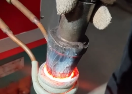
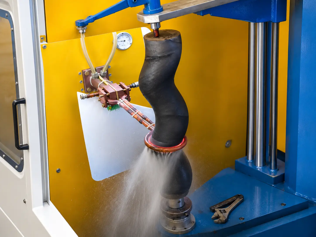
The application video shows a helical pump rotor undergoing localized induction heating and spray cooling.
The rotor is supported in a vertical position. A circular induction coil surrounds the workpiece near the lower part of the visible helical section, while liquid spray cooling is applied around the processing area.
The setup demonstrates how an induction heating and quenching arrangement can be applied to a rotor with a non-cylindrical profile.
The heating and cooling components are positioned around the selected treatment area rather than heating the entire rotor at once.
Ⅱ. Hardening a Helical-Profile Pump Rotor
Screw pump rotors are used in pumping systems where their helical geometry is essential to fluid movement.
Depending on the pump design, material and operating conditions, the rotor surface may experience mechanical contact, friction and abrasive wear. Surface hardening can be considered when the material is suitable and the application requires increased surface hardness.
The main challenge is the rotor’s irregular outer profile.
A helical thread has a raised crest and a recessed root. A round induction coil sits closer to the crest than to the root, so the eddy current density concentrates at the crest and falls off in the root. Heat builds unevenly — the crest can overheat while the root stays below transformation temperature.
Unlike a cylindrical shaft, the distance between the rotor surface and a surrounding induction coil can vary along the helical contour. This affects how the workpiece couples with the electromagnetic field and how heat is distributed.
For this reason, the heating arrangement must account for the rotor dimensions, helical geometry and location of the required hardened area.
The goal is not simply to heat the rotor, but to establish suitable heating conditions in the specified treatment region before quenching.
| Aspect | Straight Shaft | Screw Pump Rotor |
|---|---|---|
| Workpiece profile | Cylindrical, constant diameter | Helical thread with crest and root |
| Coil-to-workpiece clearance | Constant around the part | Varies between crest and root, and along the helix |
| Eddy current distribution | Even around the circumference | Concentrates at the crest, drops in the root |
| Heating uniformity | Easier to hold even | Needs rotation plus a coil shaped to the profile |
| Machine motion | Rotate and scan axially | Rotate and scan following the helix |
| Main process risk | Uneven case depth at the ends | Crest overheating, soft root |
Ⅲ. Induction Heating and Spray Quenching
The visible processing arrangement combines a ring-shaped induction coil with a nearby liquid spray cooling system.
Localized Induction Heating
The induction coil delivers electromagnetic energy to the selected section of the rotor. Its dimensions and position are important because the changing helical profile affects the clearance between the coil and the workpiece.
Heating power, frequency and heating time are selected according to the rotor material and required treatment area. For a case depth of 1.5–3 mm, the frequency typically falls in the 3–10 kHz range — higher frequency for a shallower case, lower frequency for deeper penetration.
Spray Quenching
Liquid spray cooling is arranged near the induction heating zone. The quench medium is usually water or a polymer (PAG) solution; concentration and spray pressure set the cooling rate and, with it, the final hardness.
For suitable hardenable steels — typically medium-carbon and low-alloy grades in the 0.40–0.60% C range, such as 42CrMo (AISI 4140) or 45# carbon steel — controlled heating followed by appropriate rapid cooling can produce a hardened surface structure of 50–58 HRC.
The cooling arrangement must accommodate the rotor profile and provide the required cooling conditions in the treated region.
The final hardening pattern, surface hardness and effective case depth are established through process development and workpiece inspection.
Ⅳ. Induction Coil and Workpiece Positioning
For a screw pump rotor, the induction coil and workpiece fixture must be considered together.
The coil needs sufficient clearance around the helical profile while maintaining an effective heating relationship with the selected surface.
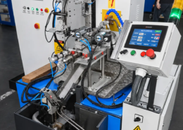
The workpiece fixture holds the rotor in the required orientation and provides access to the heating and cooling area.
In this application, the vertical arrangement allows the induction heating assembly and spray cooling components to be positioned around the rotor.
Additional machine movement, where required, is determined by the rotor geometry, treatment length and processing method.
In most setups the rotor rotates during heating so every point on the circumference passes through the coil’s field evenly. For a longer helical section, either the coil or the rotor traverses axially in a scanning pass, with the scan speed matched to the heating time so the required temperature is reached before the spray quench.
KECHUANG develops induction heating equipment, coil arrangements and workpiece tooling for different shaft and rotor hardening requirements.
Ⅴ. Customized Induction Hardening Solutions for Screw Pump Rotors
A suitable hardening process starts with the rotor drawing and material specification.
The main factors include the rotor’s helical geometry, required treatment area, target hardness, effective case depth and production requirements.
These details help determine the induction coil, workpiece fixture, heating conditions and quenching arrangement.
Request a Screw Pump Rotor Induction Hardening Solution
For a technical evaluation, please provide:
KECHUANG can evaluate a suitable induction heating and quenching arrangement for your rotor and production requirements.
Frequently Asked Questions
Click a question to expand the answer.
What materials can be screw-pump-rotor induction hardened?
Medium-carbon and low-alloy steels that respond to rapid quenching — typically 0.40–0.60% C grades such as 42CrMo (AISI 4140) or 45# carbon steel.
What surface hardness and case depth are achievable?
With the right steel and quench, 50–58 HRC at the surface with an effective case depth of about 1.5–3 mm. Both depend on frequency, heating time and the quench medium.
Why does the rotor rotate during hardening?
Rotation evens out heating around the circumference, so no point on the thread crest stays in the strongest field long enough to overheat.
Can one ring coil harden the whole helical section, or is scanning needed?
A short treatment zone can be hardened with a single ring coil held in place. For a longer helical section, the coil or the rotor scans axially, with the scan speed matched to the heating time.
Send Your Rotor Drawings
Get a technical evaluation of your helical-profile pump rotor hardening requirements.