Engine Valve Stem Tip Induction Hardening Machine for Improved Wear Resistance
Ⅰ. Engine Valve Tip Hardening Machine in Operation
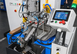
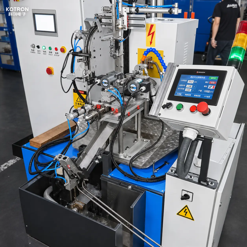
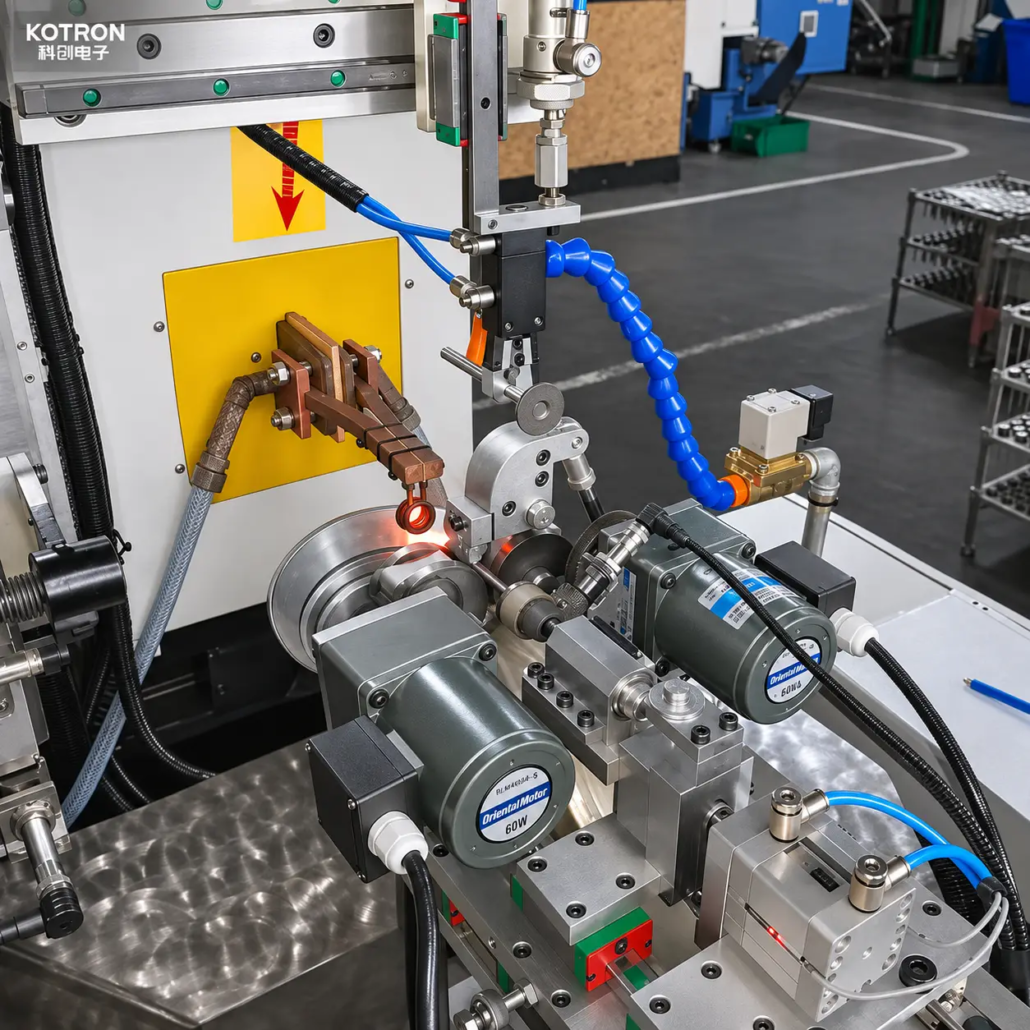
The customer-site video shows a dedicated induction hardening station processing engine valve stem tips.
The valve is held in a workpiece fixture and positioned relative to the induction coil. During operation, the designated stem tip area is heated locally rather than treating the entire valve stem.
The visible machine includes the induction heating assembly, workpiece holding components and mechanical positioning structures.
The video demonstrates the workpiece positioning and localized heating operation. The quenching arrangement and its operating conditions are established as part of the complete hardening process.
Ⅱ. Application and Workpiece Requirements
Engine valve stem tips are contact surfaces within the valve actuation mechanism. Repeated mechanical contact can cause wear at the tip, making local surface hardness an important requirement for suitable valve designs.
Induction hardening is used to develop a hardened area at the stem tip while limiting heating to the region that requires treatment.
This machine is intended for engine valve tip hardening applications where the workpiece material is suitable for induction hardening and the required treatment area can be reached by the induction coil.
Important workpiece considerations include:
•Valve material and initial heat treatment condition
•Stem diameter and overall valve geometry
•Location and length of the required hardened zone
•Required surface hardness and effective case depth, where specified
•Production quantity and workpiece handling requirements
Different valve materials and constructions may require different heat treatment methods. Suitability must be confirmed before selecting the induction hardening process.
Ⅲ. Induction Heating and Quenching Process
The machine is developed around the relationship between the valve stem tip, induction coil and quenching arrangement.
Workpiece Positioning
The fixture holds the engine valve in the required orientation and locates the stem tip relative to the heating zone. Positioning must accommodate the valve geometry and the specified treatment area.
Localized Induction Heating
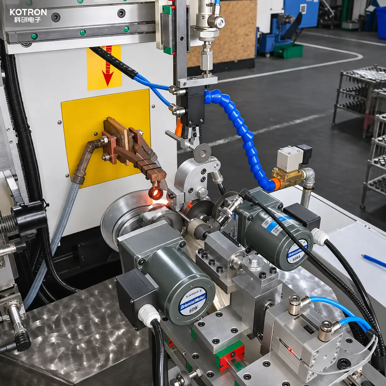
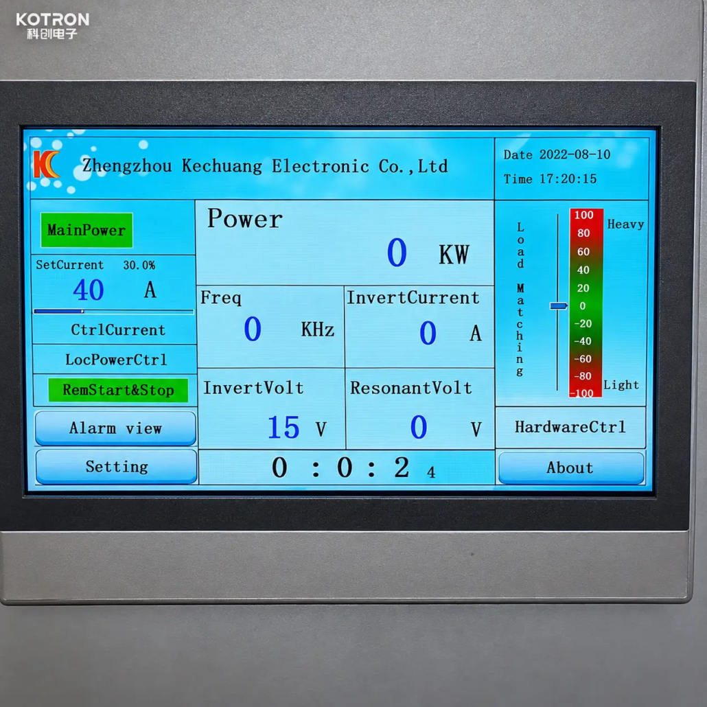
The induction coil produces heat in the conductive workpiece through an alternating electromagnetic field.
Heating is concentrated near the valve stem tip. Coil geometry, power, frequency and heating time are selected together to establish the required heating pattern.
For suitable hardenable steels, the treated region must reach the appropriate thermal condition before quenching.
Quenching
The heated tip is cooled under conditions selected for the valve material and required hardened zone.
The quenching arrangement must work with the heating sequence and workpiece positioning. The cooling method, delivery position and timing are determined during process development.
Heating and quenching parameters are established through workpiece trials and verification against the specified hardening requirements. The equipment alone does not guarantee a particular hardness or case depth.
Ⅳ. Induction Coil, Fixture and Workpiece Positioning
The induction coil and fixture are central to the machine design because the required treatment area is limited to the end of the valve stem.
Induction Coil Design
The inductor is selected according to the stem diameter, heating-zone dimensions and available working space.
Its geometry and position influence the heated area and the transition between the treated tip and the rest of the stem.
Dedicated Workpiece Fixture
The fixture holds the engine valve during processing and maintains the required relationship between the stem tip and induction coil.
Clamping position, workpiece orientation and accessibility must be considered when developing the tooling.
Machine Movement
The positioning mechanism supports the required relationship between the workpiece and heating assembly during the operating sequence.
The necessary movement arrangement is selected for the specific equipment design. A fixed-position hardening application does not automatically require the same motion system as a scanning shaft hardening machine.
Heating and Quenching Coordination
The induction heating assembly and quenching arrangement must be positioned and operated to suit the required hardened area.
Coil access, cooling delivery and workpiece handling are evaluated together rather than treated as separate equipment decisions.
Ⅴ. Machine Configuration and Customization
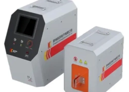
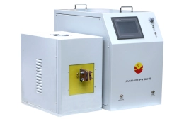
An engine valve tip induction hardening machine integrates electrical heating equipment with workholding and the mechanical systems needed for the selected process.
The customer-site equipment demonstrates a dedicated induction heating station with a workpiece fixture and positioning mechanism. The complete supply configuration is determined by the project requirements.
| System | Equipment Function or Configuration |
|---|---|
| Induction Power Supply | Supplies energy for localized heating; power and frequency are selected for the application |
| Induction Coil | Designed to heat the specified valve stem tip area |
| Workpiece Fixture | Supports and positions the valve during processing |
| Positioning Mechanism | Arranged according to the required workpiece and heating positions |
| Quenching System | Cooling method and delivery arrangement selected for the hardening process |
| Process Control | Heating sequence and operating functions specified for the selected machine |
| Automation Options | Workpiece loading, unloading or production-line integration evaluated when required |
The coil and fixture are adapted to the workpiece rather than selected solely from the induction power rating.
Additional functions such as automatic handling, programmable movement and production-line integration are project-specific. They are not assumed to be standard features of the machine shown in the customer-site video.
Ⅵ. How to Select the Right Valve Tip Hardening Machine
Machine selection begins with the valve material and the required hardened area.
The material determines whether induction hardening is suitable and influences the heating and quenching process. The stem diameter and hardening-zone dimensions guide the coil and fixture design.
Required production quantity also affects the equipment layout. A dedicated processing station may suit one application, while another project may require additional handling or integration with existing production equipment.
Where the customer has defined hardness, effective case depth or inspection requirements, these specifications should be included in the equipment evaluation.
Process trials may be required to establish the heating conditions and verify the hardening result before finalizing the machine configuration.
Ⅶ. Request an Engine Valve Tip Induction Hardening Solution
KOTRON provides customized induction heating equipment and dedicated tooling for engine valve stem tip hardening applications.
To discuss a suitable machine, please send us:
•Workpiece drawings or photos
•Valve material
•Main dimensions, particularly the stem diameter
•Required hardening area
•Expected production quantity
If available, please also include target hardness, effective case depth and inspection requirements.
Our engineering team can evaluate the induction coil, fixture, heating and quenching arrangement, and equipment configuration according to your workpiece and production needs.
Request a Customized Valve Tip Induction Hardening Machine
Send your valve drawings and specifications for a tailored engine valve stem tip hardening solution.