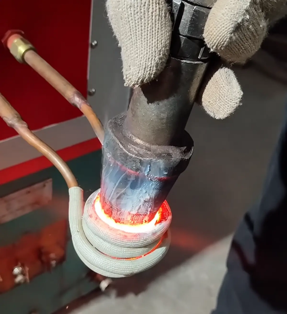
Induction Heating System for Carbide Tip Removal
Ⅰ. See Carbide Tip Removal in Operation
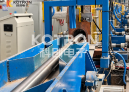
The following video shows two different brazed-tool applications.
Carbide Tip Removal from Cutting Picks and Brazed Cutting Tools
Induction Debrazing Process
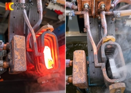
The carbide tip is attached to the end of the steel pick by brazing. During removal, the joint area is heated until the brazing alloy softens or melts sufficiently for the carbide tip to be separated from the steel body. The second workpiece is a brazed cutting tool with a different shape and joint arrangement, so its coil position and heating settings differ from those used for the cutting pick.
Both applications use the same basic process, but the heating setup follows the actual brazed joint rather than carbide size alone.
Ⅱ. How Induction Debrazing Works
A typical brazed carbide tool consists of a steel body, brazing alloy and carbide component.
For removal, an induction coil is positioned around or near the brazed joint. Electromagnetic induction heats the conductive material in the target area, transferring heat to the joint until the brazing alloy reaches a condition where the carbide component can be removed.
This process is commonly referred to as induction debrazing or induction de-brazing.
The required heating cycle depends on the actual tool, including:
•Tool size and mass
•Carbide dimensions
•Brazed joint geometry
•Brazing alloy
•Coil position
•Required processing cycle
The aim is to heat the joint sufficiently for separation without applying more heat to the surrounding workpiece than the process requires.
Ⅲ. Typical Tools and Applications
This type of induction heating system is intended for steel tools and wear components with brazed carbide parts.
Typical applications include:
•Cutting picks with brazed carbide tips
•Brazed carbide cutting tools
•Carbide-tipped wear parts
•Other carbide-to-steel brazed assemblies
For a cutting pick, the joint is concentrated around the carbide tip at the end of the steel body.
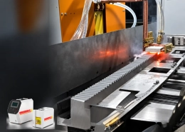
Other tools may use a longer, flatter or less accessible brazed joint. These differences affect how the workpiece is positioned and how the induction coil is shaped.
After removal, the carbide may be collected for inspection, material recovery or further processing. Removal does not by itself mean that a used carbide component is suitable for reuse.
Ⅳ. Why Use Induction Heating for Carbide Removal?
Induction heating can concentrate heat around the brazed connection without requiring the complete tool to remain in a furnace for an extended heating cycle.
Targeted heating
The induction coil can be arranged around the joint or nearby target area according to the workpiece geometry.
Fast heating response
Once the appropriate coil and process settings have been established, the joint area can be brought to the required heating condition quickly.
Adjustable process parameters
Power output and heating time can be adjusted during process development and set for repeated workpieces.
Suitable for repetitive processing
When the same type of tool is processed in batches, dedicated fixtures and positioning mechanisms can be added to keep the joint in a repeatable position relative to the coil.
The process depends on the heating pattern around the brazed joint. Increasing power alone does not determine whether the carbide can be removed effectively.
Ⅴ. Induction Coil and Workpiece Positioning
The induction coil should be selected together with the workpiece fixture.
A cutting pick and a flat brazed cutting tool may use the same debrazing principle but require different inductors.
Coil design is influenced by:
•Workpiece shape
•Carbide size
•Joint position
•Available clearance around the joint
•Required heated area
•Loading and positioning method
For some workpieces, the coil can surround the joint area. Others may require an open or specially shaped inductor because the joint can only be approached from one side.
The position of the workpiece relative to the coil also affects the heating pattern. For repeated production, the fixture should keep this relationship as consistent as practical.
Ⅵ. Power Supply and System Configuration
The induction power supply should be selected from the complete workpiece and process requirement rather than carbide-tip diameter alone.
Relevant factors include the steel body, carbide size, brazed area, heating cycle and required production rate.
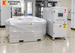
The system can be configured with an IGBT induction power supply and DSP digital control for adjustable power output and heating-time control.
Depending on the selected configuration, additional functions may include:
— Temperature monitoring
— Process-parameter monitoring
— PLC communication
— Dedicated workpiece fixtures
— Positioning or handling mechanisms
For repetitive production, the heating unit can be integrated with suitable fixtures and workpiece-handling equipment according to the required level of automation.
There is no single power or frequency setting suitable for every carbide-removal application. Final selection should be based on the actual brazed tool and joint.
Ⅶ. What Information Is Needed for Equipment Selection?
A clear tool photo or drawing is usually the best starting point.
| Information | Why It Matters |
|---|---|
| Tool photo or drawing | Shows the overall geometry and available coil access |
| Steel body dimensions | Helps evaluate heating load and workpiece positioning |
| Carbide dimensions | Defines the size of the brazed component |
| Brazed joint location | Determines coil position and access |
| Brazing alloy, if known | Helps evaluate the heating requirement |
| Required production rate | Affects fixture and handling configuration |
| Automation requirement | Helps define the machine arrangement |
If the brazing alloy is not known, the application can still be evaluated from the available workpiece information and process requirement.
Different tools may use the same induction power supply while requiring separate coils, fixtures or heating settings.
Ⅷ. Frequently Asked Questions
Click a question to expand the answer.
Can the carbide tip be reused after removal?
Possibly, but the removed carbide should be checked for wear, cracks, chipping or other damage before reuse is considered.
Can one induction system process different tool sizes?
In some cases, yes. Different tools may still require separate coils, fixtures or process settings.
Does every brazed carbide tool require the same removal temperature?
No. The required heating condition depends on the brazing alloy, joint design, tool mass and heating arrangement.
Is induction debrazing the same as carbide recovery?
No. Induction debrazing describes the heating and separation process. Carbide recovery describes one possible purpose after the carbide has been removed.
Can the removal process be automated?
Automation can be evaluated for repetitive production. Depending on the application, this may include workpiece positioning, timed heating and handling mechanisms.
Ⅸ. Send Us Your Tool Photo
If you need to remove a brazed carbide tip or carbide component from a steel tool, send us a photo or drawing of the workpiece.
For an initial evaluation, the tool dimensions, carbide size, joint location and approximate production requirement are usually enough to begin discussing the heating method and equipment configuration.
Based on the workpiece, the induction power supply, operating frequency, coil design and tooling can be evaluated together.
Send Us Your Tool Photo
Send a photo or drawing of your brazed carbide tool. We’ll evaluate the heating method, coil design and equipment configuration for your application.