Brake Shoe Induction Hardening Machine for Automotive and Commercial Vehicle Drum Brakes
Ⅰ. See the Brake Shoe Induction Hardening Process
Brake Shoe Induction Hardening
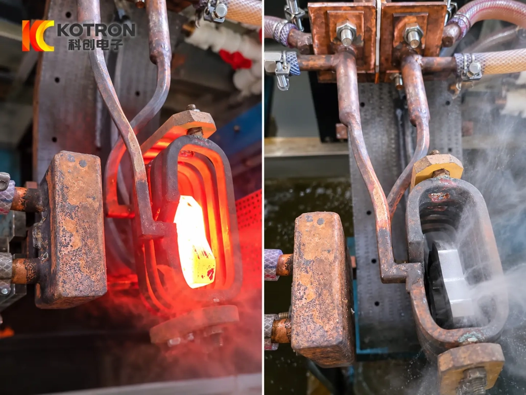
Localized Heating and Quenching
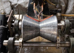
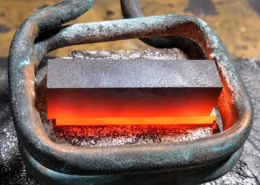
This application shows localized induction heating on a curved brake shoe profile. A contoured inductor follows the required treatment area, and the heated zone is quenched as part of the hardening cycle.
The exact heating position and movement arrangement are selected according to the brake shoe geometry and the area specified for hardening.
Ⅱ. Localized Hardening for Different Brake Shoe Designs
Brake shoe geometry can vary considerably between different models. Changes in radius, arc length, width, section thickness, hole pattern or end geometry can affect both the tooling and the heating process.
The equipment can be developed for brake shoes with different:
•Curved profiles and radii
•Widths and section dimensions
•Hole and slot arrangements
•End geometries
•Required hardened areas
•Loading and handling requirements
The hardening zone should be defined from the customer drawing or heat-treatment specification.
In some brake shoe designs, localized hardening may be required around an end, contact area, cam-related area, anchor-related area or another specified position. These locations vary by component and should not be assumed from the brake shoe name alone.
This is why brake shoe induction hardening equipment is normally designed from the actual part and treatment requirement rather than selected only by workpiece size.
Ⅲ. Customized Inductor and Fixture Design
The inductor and fixture have a direct relationship with the brake shoe geometry.
Inductor Design
For curved or irregular brake shoe profiles, a contoured inductor can be designed around the required heating area. The coil shape, working clearance and position are selected to match the local treatment zone.
A different radius or hardened position may require a different inductor, even when the parts are both classified as brake shoes.
Where several related brake shoe models need to be processed, tooling compatibility can be evaluated from the drawings. In some cases, different inductors can be used on the same machine; in others, the mechanical arrangement may also need to change.
Fixture Design
The fixture holds the brake shoe in a defined position relative to the inductor and quenching system.
Its design considers:
•Workpiece profile
•Available locating points
•Hardening position
•Loading direction
•Required movement
•Changeover between part models
For repeated production, the fixture arrangement can also be designed around the required loading and cycle method.
Ⅳ. Controlled Heating and Quenching
A brake shoe hardening cycle is not determined by induction power alone. Heating position, power and frequency, heating time, relative movement and quenching need to be considered together.
The process generally follows:
Positioning → Localized Induction Heating → Quenching → Cycle Completion
The machine movement is selected to obtain the required heating pattern. In some applications, the inductor moves relative to the brake shoe; other projects may use a different positioning arrangement.
The movement method is therefore part of the process configuration, not a fixed requirement for every machine.
The quenching system is also designed around the treated area and workpiece geometry. Spray position, timing and sequence are coordinated with the heating cycle according to the application.
Target hardness, effective case depth and hardened pattern should be defined from the customer’s technical requirement and confirmed during process development.
Ⅴ. Automatic Brake Shoe Induction Hardening for Production
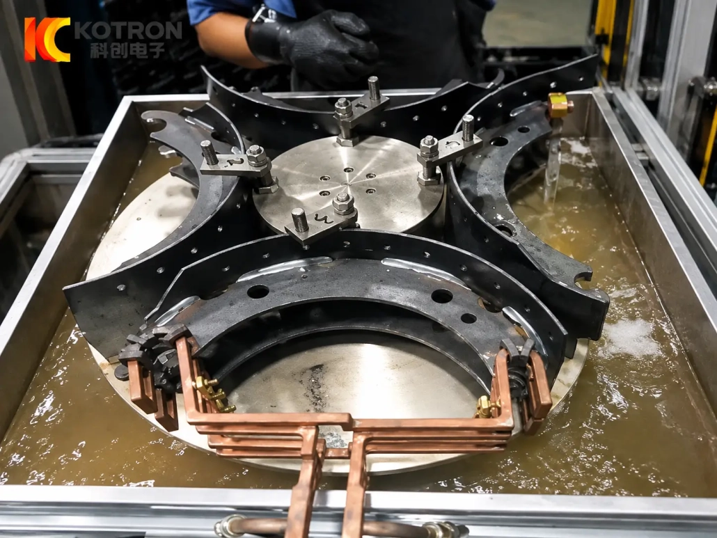
Automatic Brake Shoe Induction Hardening
Automated Heat Treatment Process
For repeated production, the brake shoe induction hardening machine can be configured with automated positioning, cycle control and quenching.
The production arrangement can be developed according to:
•Required production volume
•Number of brake shoe models
•Loading and unloading method
•Fixture arrangement
•Changeover requirements
•Available factory space
•Existing production-line conditions
Manual, semi-automatic and automatic configurations can be considered.
Where required, automatic indexing, loading, unloading or transfer functions can also be integrated into the machine layout. These functions are selected from the actual production requirement rather than treated as standard equipment on every project.
Ⅵ. Machine Configuration and Digital Process Control
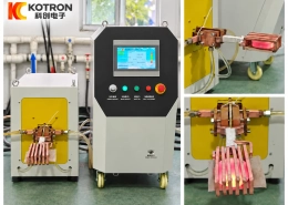
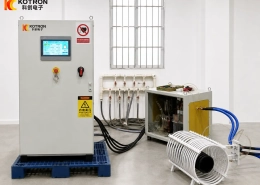
A complete brake shoe induction hardening system combines the induction power supply with the mechanical, quenching and control systems required for the workpiece.
A project can be configured with:
•Induction heating power supply
•Induction transformer
•Customized inductor
•Brake shoe fixture
•Positioning or movement mechanism
•Quenching system
•Cooling-water system
•PLC or CNC control
•HMI operating interface
•Electrical protection system
•Optional automated handling equipment
The induction power and operating frequency are selected together with the workpiece material, section dimensions, heated area, required hardening result and production cycle.
IGBT induction power technology and DSP digital control can be used according to the selected system configuration.
Process parameters may include:
•Heating time
•Power output
•Positioning sequence
•Movement parameters
•Quenching timing
•Cycle sequence
Where the control configuration supports it, recipe storage, alarm records, process monitoring and production-data functions can also be included.
These functions are useful when established hardening conditions need to be recalled for different brake shoe models or repeated production batches.
Ⅶ. What Determines the Right Brake Shoe Hardening Machine?
The most useful starting point is the actual brake shoe rather than a machine model number.
| Project Information | Used to Determine |
|---|---|
| Brake shoe drawing | Overall equipment and tooling concept |
| Radius and profile | Inductor and fixture design |
| Material and grade | Heating-process development |
| Section dimensions | Power, frequency and coil configuration |
| Required hardened area | Heating position and tooling |
| Target hardness | Process-development requirement |
| Effective case depth, if specified | Heating and quenching process |
| Number of part variants | Tooling and changeover arrangement |
| Production requirement | Cycle and automation level |
| Loading method | Fixture and handling design |
| Existing production line | Equipment integration |
| Inspection requirement | Process validation plan |
A drawing marking the required hardened area is particularly useful because two brake shoes with similar overall dimensions can still require different induction tooling or process settings.
If several brake shoe models are involved, their drawings can be reviewed together to determine whether they can share the same machine platform with different tooling and programs.
Ⅷ. Frequently Asked Questions
Click a question to expand the answer.
Can one machine process different brake shoe models?
It may be possible when the parts fall within the designed mechanical and process range. Different models can require different inductors, fixtures or process programs, so the drawings should be reviewed before the final machine configuration is selected.
Does every brake shoe require a different induction coil?
Not necessarily. Similar parts may be able to share tooling, but changes in radius, profile or hardened area can require another inductor. Coil compatibility should be confirmed from the actual part geometry.
Can the machine be configured for automatic production?
Yes. Positioning, cycle control, quenching, indexing and material handling can be automated according to the production requirement. The final automation level depends on the workpiece range and production arrangement.
What information is needed before designing the machine?
The most useful information is the brake shoe drawing, material, main dimensions, required hardened area and production requirement. If hardness, case depth or inspection requirements have already been defined, they should also be provided.
Send Us Your Brake Shoe Drawing
To evaluate the correct brake shoe induction hardening machine, send us the actual workpiece information:
Brake Shoe Drawing or Photos + Material + Main Dimensions + Required Hardened Area + Production Requirement
If available, also include:
Target Hardness + Effective Case Depth + Inspection Requirements
From these details, the induction power, frequency, inductor, fixture, movement, quenching method and automation configuration can be evaluated together.