
Induction Heating for Agricultural Machinery: Applications, Component Types, and Equipment Decisions
A combine runs 14 hours a day through soil that alternates between dry sand and wet clay. By mid-season, the drive shaft bearing journal has worn through 0.3 mm of case depth. The gear teeth next to it — same heat of steel, same dirt, same hours — still measure within spec. The difference was never the material grade. It was where the heat went during manufacturing, and how deep.
When a manufacturer hardens only the bearing journal of a 900 mm shaft and leaves the rest at its original toughness, they are making a decision a furnace cannot execute. When a repair shop frees a seized bushing by heating only the outer sleeve — not the casting around it — they save three hours of downtime and a housing replacement. Induction Heating for Agricultural Machinery earns its place in these moments: localized, repeatable, fast. The real work is deciding which parts justify it and how to engineer the process so the result at 2 p.m. matches the result at 7 a.m.
This article covers the agricultural machinery components where induction heating delivers the strongest return — drive shafts, gears, pins, blades, tines, and hydraulic assemblies. It separates hardening, brazing, and shrink fitting as distinct processes with distinct engineering requirements. And it walks through the five equipment decisions — power, frequency, coil geometry, cooling, and process control — that determine whether the line runs stable or drifts by Wednesday.
Why Induction Heating Fits Agricultural Machinery Production
Agricultural machinery manufacturers operate in a narrow band between durability and cost. A transmission shaft on a 200-horsepower tractor must survive 8,000 hours of torque reversals, vibration, and contaminated oil. A tillage tine must hold its edge through 2,000 acres of abrasive soil. A hydraulic fitting on a baler must not leak after 100,000 cycles at 250 bar. None of these parts can be over-engineered into cost oblivion. Induction heating fits because it applies energy only where failure starts — at the surface, on the wear zone, around the bearing seat — without paying for heat the rest of the part does not need.
Furnace heating works for batch processes. Flame heating works for one-off repairs. But when a production line turns out 200 shafts a day, the difference between heating a 40 mm bearing journal with induction versus soaking the entire 900 mm shaft in a furnace is not subtle. Less energy. Less scale. Less straightening after heat treat. Less floor space.
Induction does not win every comparison — very large castings, complex internal passages, and single-piece repair jobs often favor other methods.
But for medium-to-high-volume steel components, the physics tilts toward induction.
The same electromagnetic principle covered in how induction heating works is what makes induction repeatable. A furnace heats from the outside in. An induction system delivers a defined energy dose to a defined zone, cycle after cycle. Similar engineering logic drives the adoption of induction across other heavy-equipment industries, from wind power components to railway and aerospace manufacturing.
Core Applications: 6 Component Types That Justify Induction
Not every agricultural machinery part needs induction heating. The parts that do tend to share a pattern: moderate-to-high production volume, a defined wear surface or heating zone, and a failure cost that makes process consistency worth investing in. Six component families account for most induction heating applications in this sector.
1. Shafts and axles. Drive shafts, PTO shafts, and transmission shafts are the highest-volume candidates. Induction hardens bearing journals, spline ends, and seal diameters while leaving the shaft body tough. A 60 mm shaft with a hardened bearing seat at 55–60 HRC and a core at 25–35 HRC absorbs torsional shock without fracturing. For shafts over 600 mm, rotation during heating is not optional — it determines whether the case depth is concentric or lopsided. More detail is covered in shaft induction hardening.
2. Gears and sprockets. Agricultural gears operate in conditions that would qualify as abuse anywhere else — dirt through worn seals, shock loads from rocks and stumps, intermittent lubrication. Induction hardening creates a wear-resistant tooth surface while the root and core retain ductility. Tooth-by-tooth hardening handles large module gears; spin hardening covers smaller gears in a single cycle. Contour hardening follows the tooth profile for the most uniform case but demands tighter coil geometry and power control.
3. Pins, bushings, and linkage components. Loader pins, hitch pins, and pivot bushings are high-wear consumables. Induction lets the manufacturer harden only the pin surface, only the bushing bore, or both — matched to the service interval and replacement cost. The process is fast enough for in-line hardening, which simplifies production flow for high-mix part families.
4. Blades, tines, and soil-engaging tools. A tillage tine cutting through sandy loam wears differently than one hitting flint. The first needs a deep, abrasion-resistant case. The second needs enough core toughness to survive impact without snapping. Induction hardening handles both — the difference is in frequency, power density, and case depth specification, not in the fundamental process. For thin-section parts like mower blades and cultivator sweeps, the main risk is through-heating: if the entire cross-section reaches austenitizing temperature, the part becomes fully hard and brittle. Coil design and power ramping must keep the heat confined to the working edge.
5. Bearing housings, rings, and sleeves. Induction is frequently used to expand a bearing housing or ring for assembly onto a shaft or into a bore. Temperature uniformity matters more than speed — a 20°C difference around the circumference can cause the ring to cock during assembly and gall the mating surface. A pyrometer aimed at the part surface with the emissivity correctly set for the specific steel and surface condition prevents most of these problems.
6. Hydraulic fittings and brazed assemblies. Induction brazing heats the joint locally without overheating adjacent seals or thin-walled tube sections. This application is covered in detail in Section 4.
Induction Hardening: Why Wear Mode Dictates Case Depth
Induction hardening is the highest-value application in agricultural machinery manufacturing, but generic case depth recommendations do not survive contact with real field conditions. The same 1045 steel shaft that lasts 6,000 hours in a tractor transmission may fail at 800 hours in a tillage rotor. The difference is the wear mechanism — and the case depth, hardness profile, and microstructure must be matched to it.
Abrasive wear dominates in sandy and silty soils. Fine particles grind the surface like a low-grade grinding wheel. Silica in soil measures 750–1,000 HV; a surface hardened to 58–62 HRC (660–750 HV) is softer than the abrasive but hard enough to deliver an acceptable service life if the case is deep enough that wear does not reach the core. For tillage tines and cultivator sweeps in abrasive soil, 2.5–4.0 mm effective case depth is a common starting point, validated by field trials.
Impact wear is the opposite problem.
Impact wear — from stones, roots, and frozen ground — demands a different profile. A deep, fully hard case may spall or crack under repeated impact. A shallower case backed by a tougher transition zone and core absorbs impact energy by deforming slightly rather than fracturing. For a loader pin or bucket linkage component that sees frequent impact, effective case depth may be specified at 1.5–2.5 mm with a gradual hardness transition — not the steep drop-off that a poorly designed induction cycle can produce. The distinction matters: a steep hardness gradient concentrates stress at the case-core interface. A gradual gradient spreads it across a wider volume.
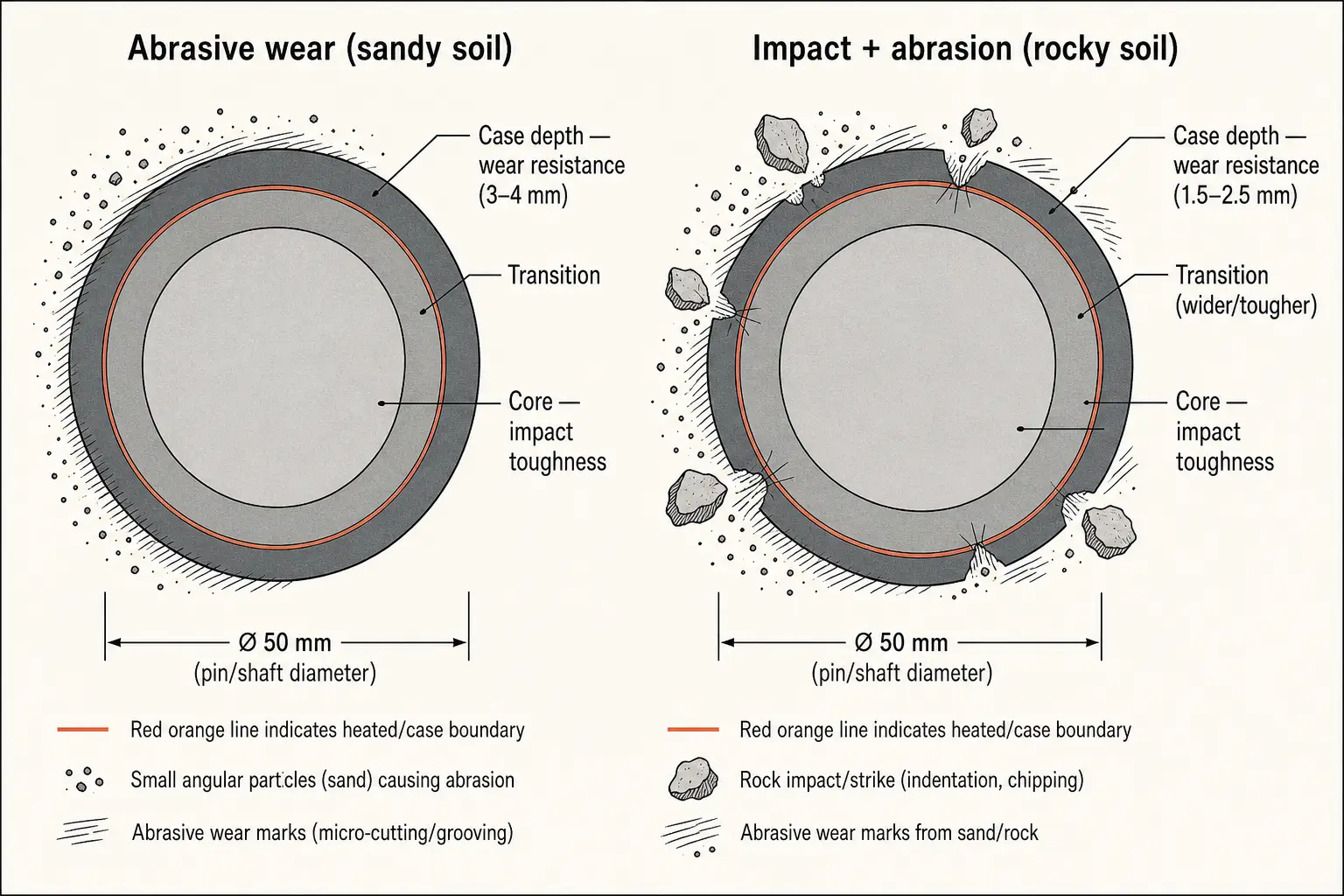
For components seeing both mechanisms — a combine auger that processes grain and the occasional stone — bias toward abrasion resistance and accept a slightly higher impact risk. Abrasive wear is the continuous failure mode; impact events are intermittent. Validate per region: a combine sold into rocky Canadian soil will not see the same wear profile as one sold into loess.
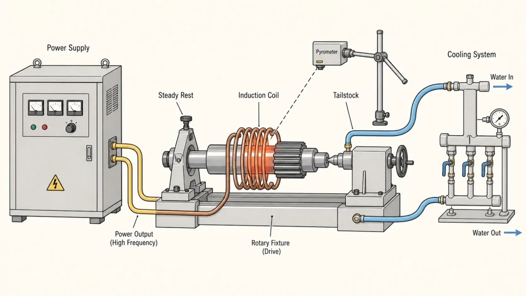
Distortion after induction hardening is a production reality for long shafts. A 1,200 mm shaft with a hardened journal at one end can bow by 0.2–0.5 mm after quenching. The fix: correct coil centering, steady rests that allow thermal expansion, uniform quench from multiple spray ports, and a post-harden straightening press while the part is still warm (150–200°C). For broader defect patterns, common induction hardening defects covers what recurs regardless of industry.
Brazing, Shrink Fitting, and Assembly Operations
Hardening gets the attention. But a significant share of induction heating in agricultural machinery manufacturing is about joining and assembly — controlled, localized heat replacing a torch flame, an oven, or a hydraulic press. Three processes dominate.
Induction brazing of hydraulic tube assemblies, manifold blocks, and sensor bosses eliminates the operator-dependent variation of manual torch brazing. The joint reaches brazing temperature in 15–60 seconds depending on mass, the filler flows, and the power cuts off. No flame impingement on adjacent seals. No soot. The cycle repeats within ±2 seconds on the next part.
Above 50 assemblies per day, an induction brazing cell with a simple fixture and foot-pedal start typically pays back within 12–18 months. Reduced rework. Lower filler consumption. Faster cycle time. The power selection principles are the same whether the braze joint is on a tractor hydraulic line or an aerospace manifold.
Shrink fitting joins components through thermal expansion. A hub heated to 200–250°C expands by a few hundredths of a millimeter — enough to slide onto a shaft that would otherwise need a press. Induction heats only the part being expanded, faster than an oven or hot oil bath. The setup decisions covered in shrink fitting machine selection apply whether the hub is going into a wind turbine gearbox or a tractor final drive.
Equipment Selection: 5 Decisions That Determine Whether the Line Runs Stable
A 100 kW induction power supply connected to the wrong coil and a poorly sized cooling loop will underperform a 50 kW system with well-matched components. Equipment selection for agricultural machinery induction heating starts with the part and the process — not the catalog rating of the power supply.
The table below provides starting-point guidance by component type. These are production baselines, not engineering specifications. Validate every entry with sample parts, hardness traverses, and temperature data before committing to production volumes.
Four parameters shape the result. Miss one and the system underperforms. Miss two and you are buying corrective coils and a larger chiller within six months.
| Component & Process | Typical Frequency | Power Range | What Goes Wrong If Underspecified |
|---|---|---|---|
| Shaft bearing journals (hardening) | 5–15 kHz | 50–150 kW | Shallow case, uneven hardness around circumference, cycle time too long for line rate |
| Gear teeth (contour or spin hardening) | 20–50 kHz | 40–120 kW | Root not hardened if frequency too high; tip overheated if power density wrong |
| Pins & bushings (case hardening) | 50–100 kHz | 20–60 kW | Through-heating on small diameters; quench cracking from excessive case depth |
| Blades & tines (edge hardening) | 20–50 kHz | 30–80 kW | Full-section hardening makes thin edges brittle; coil geometry fails to follow the edge profile |
| Hubs & rings (shrink fit) | 5–15 kHz | 30–100 kW | Non-uniform expansion, part galls during assembly; cycle time longer than press-fit alternative |
| Hydraulic fittings (brazing) | 100–300 kHz | 10–40 kW | Joint underheats at braze plane; surrounding tube wall overheats and discolors or distorts |
Frequency and power work together. For a 60 mm shaft bearing journal needing 2–4 mm case depth, 5–15 kHz puts the current penetration where it is needed. For a 15 mm pin needing 1.0–1.5 mm, 50–100 kHz concentrates the heat closer to the surface. A single frequency will not cover a product mix that spans from large shafts to small pins — many plants run two or three interchangeable output stages. Power scales with heated mass and cycle time. Most shaft and gear applications start at 50–150 kW. Small pins and brazing run on 10–60 kW. Add 15–20% margin for coil aging and part fit-up variation. More on frequency selection and power sizing in the linked guides.
Coil geometry and water cooling are where most systems deliver or disappoint. An encircling coil that fits a 60 mm shaft with 6 mm clearance couples efficiently. That same coil on a 45 mm shaft leaves a 13.5 mm gap — coupling drops, cycle time stretches. Plants running mixed part sizes need interchangeable coils or flux concentrators. The coil must survive hundreds of load cycles per shift in dust, scale, and coolant mist. Coil design is straightforward in principle; production durability is what separates five-year coils from five-week coils. Cooling keeps it all running: a system that passes commissioning in a clean demo room can trip on over-temperature three times per shift after six months in a plant that also does welding nearby. Cooling system sizing should assume the worst-case ambient temperature, not the average.
Process Control in a Production Environment
An induction heating process that works on a Tuesday morning with a freshly dressed coil, clean cooling water, and an experienced operator may not work on Thursday afternoon with a coil that has seen 800 cycles, a chiller struggling against 35°C ambient air, and a second-shift operator who was trained last week. Process control is about closing the gap between best-case and worst-case output.
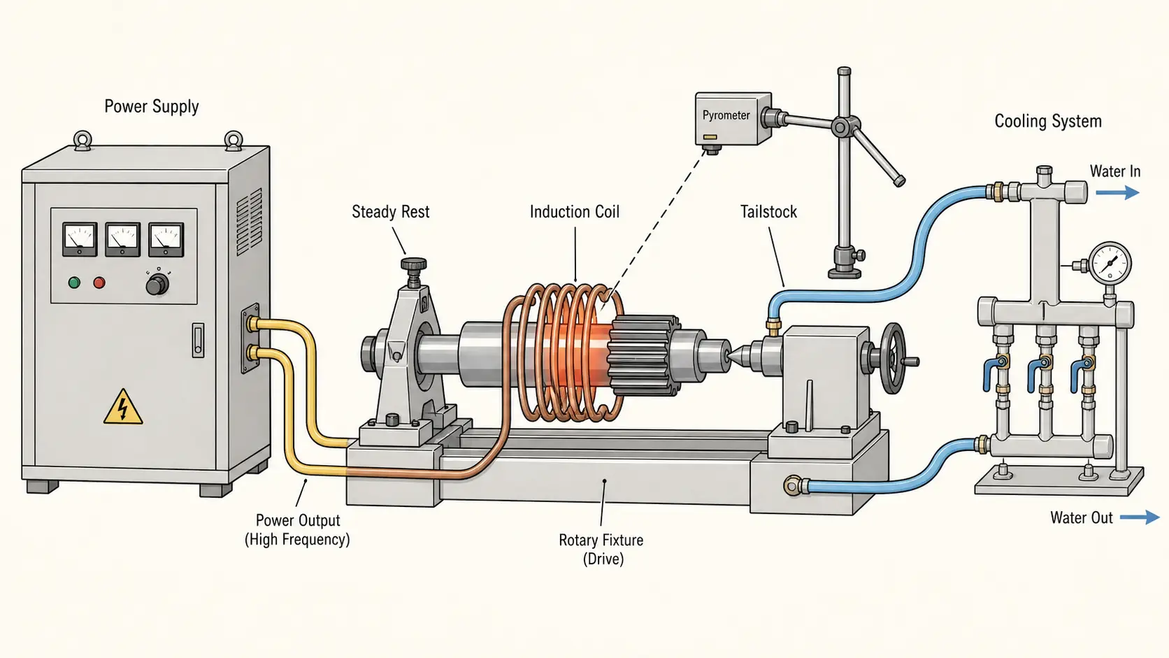
Temperature measurement is the first control loop. A single-wavelength pyrometer provides closed-loop power control — but only if the emissivity setting matches the specific steel grade and surface condition at temperature. Scale changes emissivity. A freshly machined shaft reads differently from one with light rust. Validate against a contact thermocouple at the start of each shift. Two pyrometers — one at the leading edge, one at the center — catch non-uniformities a single sensor misses.
Part handling determines whether the coil-to-part gap stays consistent. On a manual station, the operator’s technique becomes a process variable. Full automation removes that variable but adds maintenance complexity. For agricultural plants running mixed part families, the sweet spot is a manually loaded fixture with hard stops and a part-present interlock that prevents the cycle from starting if the part is not seated. Simple, rugged, fixable by the plant’s own maintenance team.
Material variation is what induction cannot fix. If the incoming steel has inconsistent hardenability, the same cycle produces different case depths. Baseline each supplier’s material separately — “4140 from Supplier A” does not harden the same as “4140 from Supplier B.” When material sources change, revalidate. A hardness traverse on the first article from a new heat costs less than a field failure.
Quality verification should match the risk. A surface hardness check, a periodic microhardness traverse, and a visual scan for quench cracks cover most hardened parts. A wear bushing needs less documentation than a transmission shaft whose failure immobilizes a $400,000 combine in the middle of harvest. For manufacturers building their first cell, how to select an induction hardening system covers the validation steps that belong at the RFQ stage.
Key Takeaway
Induction Heating for Agricultural Machinery delivers its strongest return when the process is matched to the specific wear mode, component geometry, and production volume — not treated as a drop-in furnace replacement. A shaft that needs only a hardened bearing journal does not need a furnace cycle. A gear failing from surface pitting does not need through-hardening. The five equipment decisions are what separate a line that runs stable across shifts from one that only produces good parts when everything goes right.
FAQ
Q: Which agricultural machinery parts benefit most from induction heating?
A: Drive shafts, PTO shafts, transmission gears, sprockets, loader pins, linkage bushings, tillage tines, mower blades, cultivator sweeps, bearing housings, and brazed hydraulic assemblies. The common thread: a defined wear surface on a steel component produced in moderate-to-high volumes, where localized heating provides a cost or quality advantage over bulk methods.
Q: How deep should the hardened case be on an agricultural part that sees both impact and abrasive wear?
A: There is no single number. For a tillage component in abrasive sandy soil, 2.5–4.0 mm effective case depth is a common baseline. For a loader pin or bucket linkage that sees frequent stone impact, 1.5–2.5 mm with a gradual hardness transition reduces cracking risk. The decision must be validated with field trials in the specific soil and operating conditions the machine will encounter. A part sold into rocky Canadian soil needs a different profile than the same part sold into loess.
Q: How do I choose the right induction heating frequency for agricultural components?
A: Start with the part diameter and required case depth. Large shafts (50–100 mm) needing 2–4 mm case depth typically use 5–15 kHz. Smaller pins (10–25 mm) needing a shallow case use 50–100 kHz. Gears fall in the 20–50 kHz range depending on module size. A single frequency will not cover a product mix that spans from shafts to pins. Many plants run interchangeable output stages or a variable-frequency supply. Validate with sample parts and hardness traverses before committing.
Q: Can induction hardening reduce distortion on long agricultural shafts compared to furnace hardening?
A: Generally yes, because induction heats only the zone being hardened rather than the entire shaft. But distortion still occurs if the coil is off-center, quench delivery is uneven, or the shaft is not properly supported during heating and cooling. For shafts over 600 mm, rotation during heating, steady rests that allow thermal expansion, and a post-harden straightening station for parts that must hold runout under 0.1 mm are standard practice. The straightening operation is faster and less risky when the part is still warm.
Need an Induction Heating Process for Your Agricultural Component?
Send us your part drawing, material grade, target hardness or temperature, and production rate. Our engineering team will recommend frequency, power, coil configuration, and a cooling and handling concept that fits your plant.


