
Induction Heating for Durable Wind Power Components
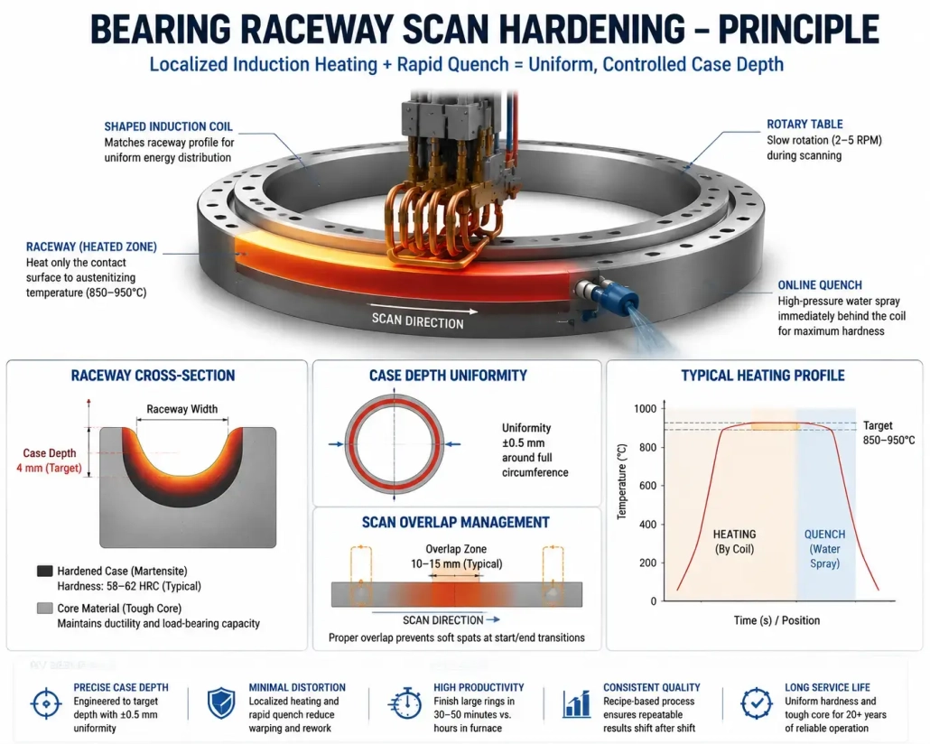
A 4-meter pitch bearing ring for an 8 MW offshore turbine weighs 3.5 tons. Its raceway needs a 4 mm hardened case, uniform within ±0.5 mm around the full circumference. The furnace option: load the ring, heat the entire 3.5-ton part to 880°C, soak for 2 hours, quench, temper — a 6-hour thermal cycle that distorts the ring enough to require 0.5 mm of post-grinding. An induction heating for wind power components approach scans a coil along the raceway at 200 mm/min, heats only the contact surface to depth, quenches inline, and finishes the ring in 40 minutes. Distortion drops. Throughput triples. Post-grinding is measured in microns, not half-millimeters.
Table of Contents
1. Why Wind Components Break Standard Heating Approaches
A pitch bearing ring runs 2 to 5 meters in diameter. A main shaft journal is 400 to 800 mm across. A planetary gear blank weighs 2 tons before the first machining pass. These are not parts you load into a benchtop induction scanner.
Size is only the first problem. Geometry is the second. Bearing raceways are curved grooves. Gear teeth have flanks, roots, and tips — each with different mass and heat-sink behavior. A coil that heats a cylindrical shaft journal evenly will miss the edges of a raceway groove. The coil must follow the feature, not just encircle the part.
Then there is the cost of getting it wrong. A gearbox or main bearing replacement on an offshore turbine involves weeks of downtime, a crane mobilization, and lost generation. The heating process carries disproportionate quality risk: an under-spec case depth or a soft spot in a bearing raceway may not surface until year 7 of a 20-year design life. When it does, the heat-treat record — if it exists — is the first thing the failure analysis team requests.
Furnace heating avoids some of these problems by heating everything. It creates others. Distortion from hours of soaking. Scale on machined surfaces. Cycle times long enough that heat treatment, not machining, sets the pace of the factory. Induction heats only the feature that needs it, in minutes, and integrates quench and handling in one station. The tradeoff: it demands precise positioning, the right frequency, and enough power to outrun a multi-ton heat sink.
2. Induction Heating Applications in Wind Turbine Manufacturing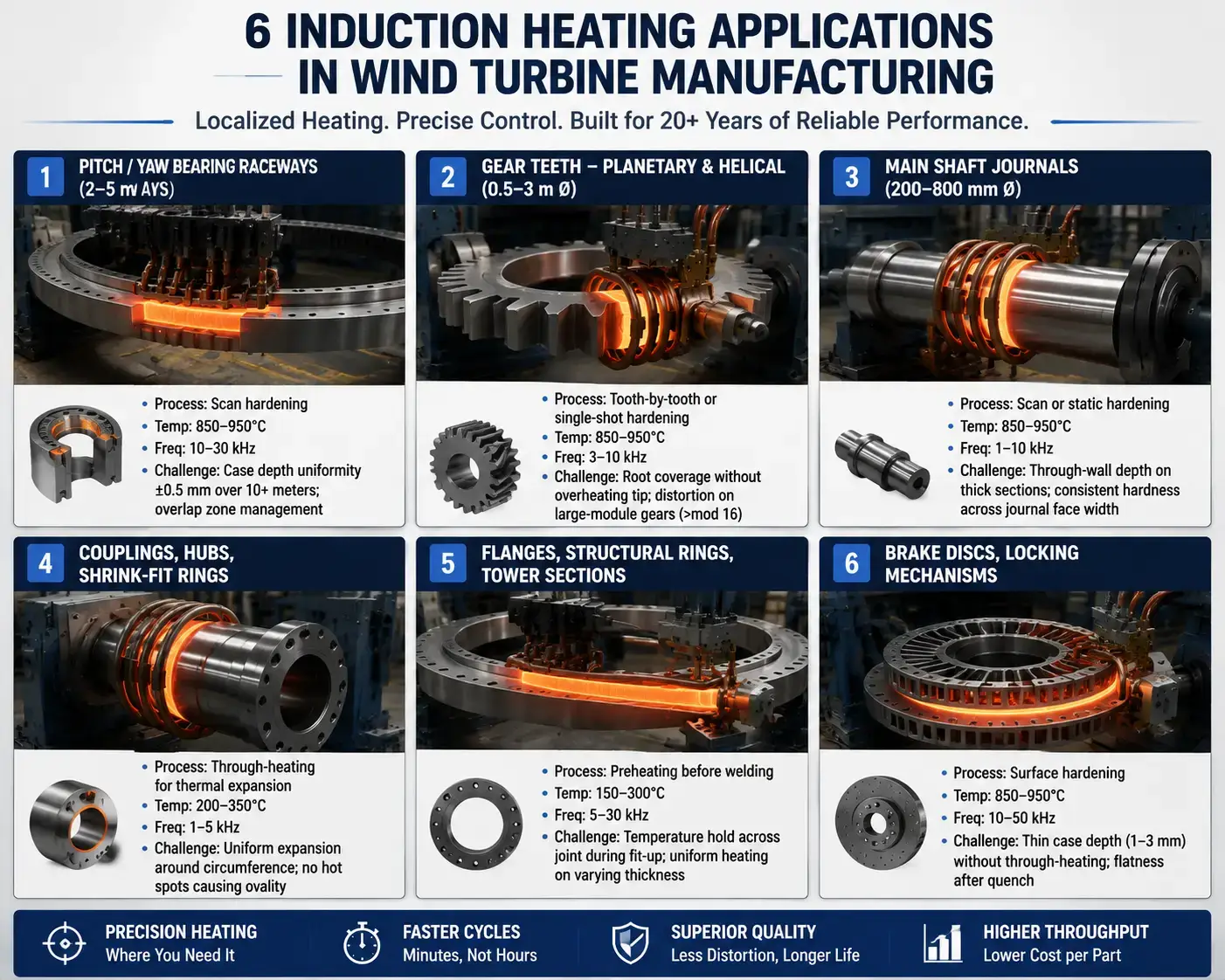
The six applications mapped above span every major drivetrain component from the main shaft to the brake disc. Bearing raceways, gear teeth, and shaft journals dominate the hardening side. Couplings, hubs, and shrink-fit rings account for most assembly heating. Flanges and tower sections use induction for pre-weld preheat. Each application demands a different frequency, power density, and coil geometry — the table in Section 4 covers the electrical side of those decisions.
3. Component Scale: Diameter, Mass, and the Access Problem
Diameter dictates everything downstream. A coil for a 4-meter pitch bearing ring must maintain a 2–5 mm air gap around a curved raceway groove while the ring rotates at 2–5 RPM on a turntable. That same coil will not heat a 2-meter ring efficiently — the air gap becomes too large. Mills running a range of ring sizes keep multiple coils: one for small-bore, one for mid-range, one for large-bore. The same challenge shows up in induction heating large rings: diameter drives coil inventory and handling design.
Mass is the heat sink you are fighting. A 3.5-ton bearing ring at room temperature pulls heat away from the raceway surface faster than the induction coil can deliver it — unless the power supply is sized correctly. For a 4-meter ring, 200–500 kW is typical for raceway scan hardening. Undersize by 30% and two things happen. The surface may never reach austenitizing temperature at the target scan speed. Or it reaches temperature so slowly that the heat-affected zone spreads beyond the specified case depth, and the hardness profile fails metallurgical inspection.
And then there is access. Can the coil physically reach the surface? A main shaft journal has open OD access. A planetary gear internal spline does not — a standard encircling coil will not fit. Internal bores, blind shoulders, and recessed surfaces need ID coils or pancake conductors that squeeze into the available space. The coil must clear the part, the fixture, the quench ring, the pyrometer sight line, and the crane loading path. In practice, fixture interference constrains coil geometry more often than the part itself does.
4. Frequency, Power, and Coil Design for Large Components
Change the frequency and the coil design impedance shifts. Change the coil geometry and the power requirement moves. On a wind component where one scrapped part erases the margin on a dozen good ones, frequency, power, and coil geometry are engineered as a single system.
- Frequency follows case depth. Bearing raceways at 2–6 mm case depth operate in the 10–30 kHz range. Gear teeth needing 3–8 mm at the root run 3–10 kHz. Shrink-fitting — where the goal is through-heating for uniform thermal expansion, not a hardness gradient — uses 1–5 kHz. These are starting points. Material grade shifts the number: 42CrMo4 (4140) behaves differently from 18CrNiMo7-6, the workhorse carburizing steel for wind turbine gears. Our frequency selection guide covers the depth-frequency relationship.
- Power sizing starts from the worst-case component, not the average. A manufacturer running three bearing ring sizes on the same machine — 2-meter, 3.5-meter, and 5-meter — must size the power supply for the 5-meter ring at the required scan speed. For reference: scan hardening a 5-meter pitch bearing raceway to 4 mm case depth at 180 mm/min requires roughly 400–600 kW. Running the same ring at 300 mm/min needs 700–900 kW. Adding 15–20% margin for coil aging and line-voltage variation puts the system at 500 kW to 1.1 MW depending on throughput targets. Our power selection guide walks through the calculation.
- Cooling water separates production uptime from downtime. At 400–800 kW output, the coil, power supply, capacitors, and buswork generate substantial heat. The water cooling system circulates 60–150 L/min through the coil alone. Water quality thresholds: conductivity below 300 µS/cm, pH 6.5–8.0, suspended solids under 10 mg/L. Redundant pumps, per-circuit flow switches, and ΔT monitoring are production minimums. When a cooling circuit fails on a coil heating a 5-meter ring mid-cycle, the copper anneals in seconds — and the ring may need salvage evaluation.
5. Shrink Fitting, Assembly, and Field Repair
Shrink fitting — heating a coupling, bearing inner ring, or sleeve to expand it onto a shaft — is as common in wind turbine work as hardening. The physics: a steel ring at 250°C expands roughly 0.15 mm per 100 mm of diameter. A 500 mm coupling bore opens by 0.75 mm. That clears an interference fit of 0.3–0.5 mm.
Uniform heating is what makes it work. A torch on one side creates a hot spot, ovality, and a stuck part. An induction coil around the full circumference — with the part centered — delivers even expansion. 50–200 kW at 1–5 kHz through-heats the wall in 2–8 minutes. Check temperature at 3–4 points before lifting.
Field repair turns the same physics into a harder problem. A main bearing fails in a nacelle 100 meters up. No crane can lower the full drivetrain. Portable induction — 30–100 kW, air-cooled or compact water-recirculated — heats the bearing inner ring in place. Cycle time: 5–15 minutes. The alternative: cutting the bearing off with a grinder, or a torch inside a nacelle full of oil mist.
6. Handling and Positioning
A 4-meter bearing ring lands on a crane, settles onto a turntable with roller supports, and must center to ±1 mm of the coil before the scan starts. The turntable, coil mount, quench ring, and pyrometer arm all compete for space around the part. If loading and unloading adds more than 2–3 minutes to the cycle, throughput targets are unreachable.
Positioning is not a setup step. It is the process.
On a bearing raceway scan system, the coil-to-part gap runs 2–5 mm. If the turntable bearing has 0.5 mm radial runout, the gap varies ±0.5 mm around the circumference. Surface temperature shifts ±8–15°C. Case depth walks by 0.3–0.5 mm. Turntable runout, roller wear, ovality — each contributes. The preventive maintenance schedule must cover the handling system with the same rigor as the power supply.
7. 5 Common Problems and How to Prevent Them
| Problem | Root Cause | Prevention |
| Case depth variation >1 mm around raceway circumference | Coil-to-part gap variation from turntable runout or ring ovality; scan speed inconsistency | Verify turntable runout <0.3 mm TIR. Dial in coil gap at 4 points around circumference during setup. Use closed-loop scan speed control tied to rotary encoder — not open-loop motor drive. |
| Soft spots at scan overlap zone | Insufficient overlap length; power ramp-down before scan end; quench delay at start/stop transition | Program 10–15 mm scan overlap. Maintain full power through the overlap zone — do not ramp down early. Start quench flow 2–3 seconds before the coil reaches the overlap zone to ensure immediate cooling. |
| Gear tooth root under-hardened, tip overheated | Uniform coil-to-tooth gap impossible with standard encircling coil; root acts as heat sink, tip as antenna | Use shaped coil that follows tooth profile with flux concentrator at root. Reduce frequency to 3–5 kHz for deeper root penetration. Run process qualification with tooth sectioning at root, flank, and tip. |
| Shrink-fit ring sticks partway onto shaft | Uneven heating creates ovality; ring cools during transfer from heater to assembly station | Verify temperature at 3–4 circumferential points before lift. Keep transfer time under 30 seconds. Size coil for 15–20 mm radial clearance to allow part growth. Heat to 30–50°C above calculated expansion requirement as transfer-cooling buffer. |
| Distortion exceeding post-grind allowance | Excessive heat input; uneven quench; residual stress from prior machining released during heating | Use the minimum power that achieves case depth at target scan speed — not maximum available. Align quench spray pattern with heated band. Stress-relieve rough-machined rings before finish machining and induction hardening. Measure roundness before and after to establish baseline distortion per ring size. |
Most of the defect mechanisms in common induction hardening defects apply to wind components — the difference is that wind parts are larger, more expensive to scrap, and harder to fixture than automotive or general industrial components. The physics does not change. The consequences get bigger.
8. Selecting a System: The Specs a kW Rating Won’t Cover
The power rating comes after the part, the process, and the throughput are defined. Start with these inputs:
- Part drawings with material grade, dimensions, and tolerances.
- Heated area: which surface, what case depth, what hardness specification.
- Target temperature and tolerance.
- Cycle time for the largest, heaviest component in the product mix.
- Available crane capacity, floor space, and part loading path.
- Cooling water: flow, pressure, temperature, and quality at the installation point.
- Quench medium, filtration, and temperature control requirements.
Beyond the spec sheet, four things separate a system that runs shifts from one that gets debugged for a year:
- Experience at your diameter and weight class. 150 automotive CV joint systems do not prepare an engineering team for a 4-meter bearing ring and a 5-ton turntable load.
- Cooling system scope. If the quote does not include the heat exchanger, pump skid, filtration, and conductivity monitoring, it is not a turnkey system. Water quality trips are the most common cause of first-year production downtime.
- Recipe management. Storing scan speed, power, frequency, gap, and quench timing by part number eliminates shift-to-shift setup variation.
- Process development on your floor, with your parts. Lab trials on 500 mm coupons do not validate a process for a 4-meter production ring. Commissioning on your turntable, with your handling, your quench, and your metallurgical acceptance criteria is the only way to close the gap between installation and production-ready.
For broader guidance, our article on selecting an induction hardening system covers the decision framework — scaled up to wind component dimensions, the same principles apply.
Key Takeaway
Induction heating for wind power components replaces hours-long furnace cycles with minute-range localized heating — when the system is engineered around the part, not adapted from a smaller application.
Three things determine whether it works. One: can the coil reach the feature being heated? Two: can the power supply outrun the thermal conduction of a multi-ton heat sink? Three: does the handling system position the part repeatably enough that Part 47 heats the same as Part 1? The kW rating comes after those are answered.
FAQ
Q: What wind turbine components can be induction hardened?
A: Pitch and yaw bearing raceways, planetary and helical gear teeth, main shaft journals, and brake disc surfaces. The process works wherever a defined wear surface needs a controlled hardness case — typically 2–8 mm deep — on an electrically conductive steel or cast iron part.
Q: Can induction handle the large diameters in wind turbines?
A: Yes — but the handling system matters more than the power supply. A 4-meter bearing ring needs a turntable with <0.3 mm TIR runout, a coil with 2–5 mm gap control, and scan speed tied to rotary position feedback. The electrical side scales. The mechanical side is where diameter creates problems: coil sag under its own weight, turntable bearing wear, and thermal expansion of the ring changing the gap mid-cycle.
Q: Is induction faster than furnace heat treatment for wind components?
A: For localized hardening — bearing raceways, gear teeth, shaft journals — yes. A furnace cycle for a 3.5-ton ring runs 4–6 hours including soak, quench, and cool. Induction scan hardens the same ring in 30–50 minutes, heating only the raceway surface to depth. For applications requiring full through-heating of the entire part cross-section, the speed advantage narrows or disappears. The technology wins where only a specific feature needs heat, not the entire mass.
Get a Process Review for Your Wind Component Application
If you are hardening bearing rings, case hardening planetary gears, or shrink-fitting couplings onto shafts — send your part drawings, material grade, case depth spec, and target cycle time. We will evaluate frequency, power, coil geometry, and handling requirements around your largest component, not your average.


