
Induction Heating in Aerospace Manufacturing: Applications, Process Control, and Equipment Selection
You’ve got an aerospace part that needs heat in one spot. The rest of the component should stay cool. A furnace is the wrong answer to that problem.
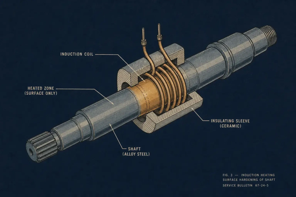
That’s where Induction Heating Aerospace Manufacturing fits. Controlled, localized energy. No soaking the whole workpiece. No waiting for a furnace to stabilize. But here’s the thing — induction isn’t plug-and-play. It’s electromagnetic. Results depend on alloy, geometry, frequency, coil design, and a dozen smaller variables that all interact. Dial them in and you get tight thermal control, less distortion, shorter cycles. Miss, and you make scrap. If you’re new to the underlying physics, how induction heating works covers the basics.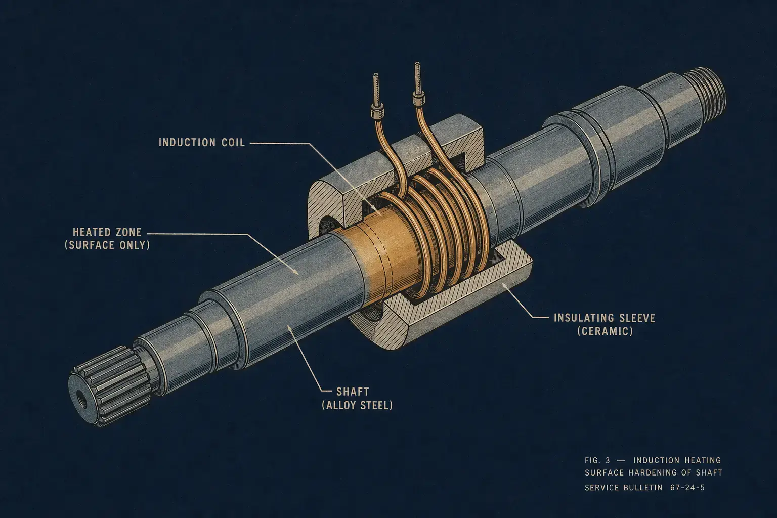
1. Why Induction Heating Fits Aerospace Manufacturing
Aerospace parts mean expensive materials, tight tolerances, and a lot of paperwork. Throw the whole part in a furnace and you’re adding thermal exposure it never needed — more distortion risk, longer cycles, more handling.
Induction heats the workpiece directly with electromagnetic energy. No flame. No radiant elements. The heat pattern is a function of material properties, frequency, coil geometry, part position, and power level. Get the combination right and the heat lands exactly where you want it, at the ramp rate you need, every cycle.
On the floor, engineers don’t pick induction because it sounds high-tech. They pick it because it solves specific problems that furnaces can’t touch:
— Heat one feature. Leave the rest alone.
— Cut handling steps. Shorter cycles than any furnace route.
— No combustion byproducts. Cleaner than flame.
— Recipe-driven. PLC-controlled. Repeatable.
— Traceable profiles for certified production.
The best applications aren’t where induction is faster. They’re where controlling where the heat goes — and where it doesn’t — makes the difference between a stable process and a constant headache.
2. Common Aerospace Applications for Induction Heating
Induction turns up in component manufacturing, MRO tooling, and specialty heat treatment. Across all of them, two things matter: repeatability and a heat-affected zone you can actually control. Here’s how it maps against the most common aerospace processes.
| Process | Typical Aerospace Parts | What Decides Success |
|---|---|---|
| Induction Hardening | Splines, shaft journals, gear teeth, bearing seats, actuator components | Coil design, scan speed, quench timing, frequency match to case depth |
| Induction Brazing | Tube assemblies, sensor housings, fittings, fluid-system components | Joint fit-up, filler placement, atmosphere or flux control, soak time |
| Shrink Fitting | Bearings, rings, sleeves, bushings — anything interference-fit | Predictable expansion, set-temperature shutoff, part positioning |
| Localized Preheating | Weld joints, adhesive bond lines, coating areas, composite cure zones | Thermal validation inside narrow process windows |
Induction hardening
Selective hardening puts a hard case over a tough core — exactly what wear surfaces on splines, journals, gear teeth, and bearing seats need. Only the target area hits transformation temperature, so distortion lands lower than furnace hardening. The catch: induction hardening is only as good as the coil design, scan speed, quench control, and frequency match. Change one of those and the hardness profile moves. Common induction hardening defects almost always trace back to one of those variables drifting.
Induction brazing
Tube assemblies, sensor housings, fittings, fluid-system joints — induction brazing heats the joint without cooking the rest of the assembly. Fixtures, inert atmosphere, flux, controlled joint clearance — the setup flexes around the alloy and the spec.
Reaching brazing temperature is straightforward. Keeping joint fit-up, filler placement, heating uniformity, soak time, atmosphere, and cooling rate all in spec simultaneously — that’s the part that separates a reliable process from a rework generator.
Shrink fitting
Bearings, rings, sleeves, bushings: anything with an interference fit expands cleanly under induction. No flame. No oven wait. The goal isn’t metallurgical — it’s predictable thermal expansion. Heat the outer component to a programmed temperature and the assembly drops together. Repeatable. Boring, even. That’s the point.
Bonding, curing, and preheating
Pre-weld preheat. Adhesive activation. Coating cure. All need controlled heat without the slowness or broad exposure you get from radiant heaters. Composites, coatings, thin-walled structures — these have process windows measured in single-digit degrees. Induction delivers the heat. Proving the temperature stayed where it belonged is where the real work lives.
Specialty alloy heat treatment
Steels, nickel alloys, titanium, aluminum — induction can handle the lot, but not every heat treatment spec translates to induction. Long soaks. Whole-part uniformity. Those belong in a furnace. Induction earns its keep where selective, rapid, precisely located heating is the point of the process, not a compromise.
3. Materials and Process Considerations
Start with the material. Electrical resistivity, magnetic permeability, thermal conductivity, part geometry, target temperature — those five things determine whether induction works easily, works with effort, or doesn’t make sense at all.
| Material | Magnetic Below Curie? | Thermal Conductivity | What Changes for Induction |
|---|---|---|---|
| Carbon / Alloy Steel | Yes | Moderate | Straightforward. Frequency adjusted for case depth target. Curie transition changes heating behavior mid-cycle — account for it in power profiling. |
| Nickel Alloys (Inconel 718, 625, etc.) |
No | Lower than steel | Higher power density needed. Watch for hot spots at edges and section changes. Oxidation-sensitive grades need atmosphere control. |
| Titanium Alloys (Ti-6Al-4V, etc.) |
No | Low | Rapid surface heating, but oxidation control is critical. Low conductivity means heat doesn’t spread fast — coil coupling has to be right. |
| Aluminum | No | Very high | High power, tight coil coupling required. Heat spreads fast so thin sections need careful ramp control. Not a steel setup — different animal entirely. |
In aerospace, reaching temperature isn’t enough. The heating method has to support the spec: ramp rate limits, soak time, uniformity across the heated zone, surface condition afterward, atmosphere constraints, distortion tolerance, metallurgical acceptance criteria, and the inspection and documentation trail that goes with all of it.
For critical parts, validation gets expensive. Embedded thermocouples during development. IR correlation. Hardness traverses. Microstructure. Destructive sectioning. It takes time. Budget for it.
And geometry matters as much as chemistry. Edges, corners, holes, shoulders, splines, diameter transitions — induction doesn’t heat these the way it heats a smooth cylinder. Aerospace parts have weight-reduced geometries, thin walls, tight radii. Exactly the stuff that makes uniform heating hard. Coil shape, part rotation, scanning motion, flux concentrators, power profiling — all tools in the box, but they have to be tested on actual parts. Models get you close. Parts tell the truth.
4. Frequency, Power, and Coil Design Decisions
Three decisions shape every induction process: frequency, power, and coil design. They determine where the heat lands, how concentrated it is, and how fast the part reaches temperature. Miss on any of them and the rest of the system can’t compensate.
Frequency. Higher frequencies push heat toward the surface. Lower frequencies drive it deeper. For hardening, the number you pick directly sets case depth and transition zone width. For brazing or shrink fitting, frequency controls whether the heat parks at the joint or spreads through the section. The right answer depends on material type, part diameter or wall thickness, required heating depth, cycle time, and whether you’re surface-heating or trying to heat through the whole cross-section.
A 3–10 kHz system on a 50 mm steel shaft gives you deep case capability. The same part at 200–400 kHz limits you to a thin surface layer. Neither is “better” — they do different jobs. Frequency selection walks through the trade-offs in more detail.
Power. Too little power and your cycles drag. Heat creeps into areas you didn’t want heated. Process control drifts. Too much power sitting available isn’t a problem by itself — as long as it’s controllable and matched to the coil and recipe. When sizing, stack part mass and heated volume against target temperature, cycle time, heat losses to fixtures and quench, production rate, duty cycle, and whatever part families might hit this machine down the road.
Don’t just ask “how many kilowatts.” Ask whether the system delivers repeatable energy cycle after cycle under production conditions — coils aging, water temperature shifting, operators changing shifts. That’s the metric that matters. Power selection covers sizing methodology.
Coil design. The coil is where everything meets the part. A properly spec’d power supply feeding a badly designed coil still makes bad parts. Aerospace geometries almost always demand custom coils — off-the-shelf rounds won’t give you the right pattern or clearance.
What to watch: coil shape and turn count, coupling gap, how much positioning tolerance the part has, copper tube size and cooling capacity, whether flux concentrators help, field uniformity, how the coil holds up mechanically, and whether someone can swap it out without an afternoon of realignment.
On high-value parts, coil repeatability over six months matters more than how it performs on day one. If the coil geometry walks after 500 cycles, or the spare doesn’t match the original’s heat pattern, you’ve got a quality problem that’ll show up in inspection — or worse, in service.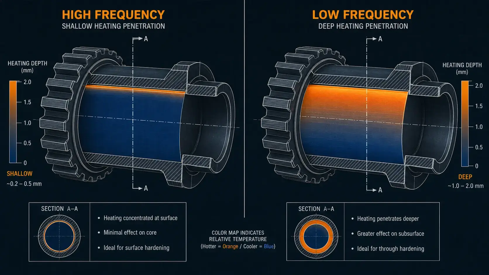
5. Process Control, Automation, and Quality Assurance
Aerospace manufacturing lives on documented process control. Induction equipment has to deliver repeatable recipes, controlled power delivery, temperature monitoring where it adds value, and traceable production data.
How much control? Depends. A shrink-fit station might only need temperature-based shutoff and part-presence confirmation. A hardening cell running flight-critical components will need power profiling, scan speed control, quench timing, flow monitoring, and locked recipes with audit trails.
Pyrometers are the default, but they’re not foolproof. Emissivity shifts, surface finish, viewing angle, steam, scale, part motion — all of it messes with the reading. Once a process is validated, a power-time recipe sometimes holds tighter than chasing a pyrometer signal that’s bouncing around. Other applications can’t function without real-time temperature feedback. Which bucket you fall into depends on the part, the material, and the quality requirement. Test it. Don’t assume.
Induction plays naturally with robotics, indexing tables, conveyors, rotary fixtures, and PLC-controlled cells. In aerospace, the stronger case for automation is almost never speed. It’s taking operator-dependent variation out of a certified process. Recipe selection by part number. Barcode or MES handshaking. Part presence confirmation. Coil position verification. Servo scan motion. Quench flow confirmation. Temperature logging. Fault interlocks. Cooling water monitoring. None of it is exotic — but all of it needs to work together without someone babysitting it.
Cooling water doesn’t get enough attention in system design. When it drifts — flow drops, inlet temperature climbs, conductivity creeps up — you get nuisance faults, cooked coils, reduced output, or heating inconsistency that’s hard to diagnose because nobody is watching the water. Flow rate, quality, conductivity, temperature, pressure, filtration: spec them. Monitor them. Water cooling systems deserve their own section of the spec sheet.
6. Equipment Selection for Aerospace Production
Start with the process, not a catalog. The right system configuration comes from your part family, your quality documentation requirements, your throughput, your floor, and who’s going to maintain it. Sample testing beats any estimate. For critical components, test data is the only thing that counts.
Before you call a supplier, have answers for these:
— What features need heat? What materials and alloys?
— Temperature, hardness, case depth, or joint criteria — which ones and how tight?
— Cycle time, production volume, duty cycle?
— Manual load, semi-auto, or lights-out automated?
— What inspection data gets recorded and where does it go?
— Utilities on site? Cooling water infrastructure?
— How many part numbers share this machine? How often do they change over?
— Coil replacement: who does it, how fast does it need to be, what’s the alignment procedure?
Those answers narrow the frequency range, power level, control platform, mechanical handling, and cooling package. Skip this and the quote you get back will be someone’s standard configuration, not yours. Equipment selection covers the broader framework.
System configuration runs from a standalone supply and coil (fine for simple heating) to a fully integrated automated cell (what validated aerospace production usually needs). One key call: how much process control stays with the induction supplier versus your in-house integration team. Get that wrong and you’re integrating twice.
Maintainability doesn’t mean “it comes with a manual.” Coils, hoses, quench parts, sensors, fixtures — all wear items. If swapping one takes half a shift and the alignment isn’t repeatable, your process drifts and your quality people notice before your maintenance people do. Look for access, clear diagnostics, documented setup parameters, and a spare coil plan that actually works. Especially if this machine is the one that feeds a bottleneck.
7. Practical Limitations and Engineering Risks
Induction isn’t the answer to every heating problem. It shines when the job is localized, repeatable, and benefits from speed. It’s the wrong tool when you need to bring a large complex part to uniform temperature and hold it there for an extended soak.
Risks that show up in the real world:
— Edges, corners, thin sections heat faster than the body of the part. Every time.
— Bad coil coupling or misaligned positioning → local overheating.
— Part-to-part geometry variation. Not all “identical” parts are identical.
— Pyrometers lie when surface finish, emissivity, or steam changes.
— Undersized quench in hardening — you won’t know until the hardness traverse fails.
— Coil overheating from water flow that looked fine on the drawing.
— Replacement coil doesn’t match the original. Process shifts. Nobody flagged it.
Most of these don’t surface during commissioning. They show up after six months of production, when someone changes a fixture, a coil gets replaced, or a new alloy variant hits the line. Application testing, sensible coil engineering, proper fixturing, and process monitoring catch a lot of them. Training catches the rest.
| If you need… | Induction | Furnace |
|---|---|---|
| Heat one specific area, rest stays cool | ✓ | — |
| Whole-part uniform temperature + long soak | — | ✓ |
| Ramp from cold to temperature in minutes | ✓ | — |
| Batch process hundreds of identical parts | — | ✓ |
| Inline automation, recipe-driven, traceable | ✓ | — |
| Controlled atmosphere (vacuum, inert gas) | — | ✓ |
In practice, a lot of shops run both. Induction handles the selective work — brazing, hardening, assembly heating, preheat. Furnaces handle whole-part thermal processing. They’re complementary. Not competitors.
Bottom line: Induction Heating Aerospace Manufacturing earns its place when you need localized heat, repeatable energy delivery, shorter cycles, and a process that integrates with controlled production equipment. The difference between a system that runs and one that runs reliably for years comes down to matching frequency, power, coil design, cooling, automation, and validation to the specific part — and the quality bar it has to clear.
FAQ
Q: What aerospace parts are good candidates for induction heating?
A: Shafts, splines, gears, bearing surfaces, bushings, sleeves, fittings, and tube assemblies — basically any component where you need to heat a specific feature rather than the whole part. The best candidates tend to be parts where selective heating directly improves dimensional stability or joint consistency compared to furnace processing.
Q: How do you choose the right induction frequency for aerospace components?
A: Frequency choice hinges on material, part geometry, required heating depth, and what you’re trying to do — surface harden, through-heat, or braze. Higher frequencies concentrate at the surface; lower frequencies penetrate deeper. Application testing on representative parts is the most reliable way to lock it in. Theoretical estimates help narrow the range, but they don’t replace real test data.
Discuss Your Aerospace Induction Heating Application
Share your part geometry, material, process target, and production rate. Our engineering team can help size induction power, frequency, coil design, and system configuration for your aerospace application.


