Induction Brazing Motor Terminals: 6 Critical Factors for Consistent Joints
Induction brazing motor terminals is a process where every second counts. Heat too fast and you burn the insulation. Heat too slow and the filler metal never flows. Get it right, and you produce clean, repeatable joints — cycle after cycle — at a pace that keeps the production line moving.
This guide walks through six factors that determine whether your motor terminal brazing process delivers consistent quality or turns into a rework bottleneck.
| 1. Why Induction for Motor Terminals | 4. Filler Metal Selection |
| 2. Key Process Parameters | 5. Coil Design and Positioning |
| 3. Temperature Control | 6. Common Defects and Fixes |
1. Why Induction Brazing for Motor Terminals
Motor terminals — whether on commutators, slip rings, or stator lead connections — need joints that can handle thermal cycling, vibration, and electrical load without degrading. Traditional torch brazing works, but it is slow, operator-dependent, and difficult to integrate into automated lines.
Induction brazing solves these problems in three ways. First, heat is generated directly in the workpiece, not applied from outside, so the joint reaches brazing temperature in seconds. Second, the heating zone is precisely controlled by the coil geometry — the insulation a few millimeters away stays cool. Third, every cycle runs the same parameters, so the fiftieth joint matches the first.
For automotive motor production, where thousands of terminals are brazed per shift, this repeatability alone often justifies the equipment cost.
2. Key Process Parameters
Induction brazing motor terminals comes down to a handful of interacting variables. Changing one shifts the others.
— Power level: Determines how fast the joint reaches brazing temperature. Too high, and you risk overheating the copper and damaging adjacent insulation. Too low, and cycle time stretches beyond what the line can accept.
— Heating time: Typically 3–15 seconds for small terminals. The sweet spot depends on joint mass, coil design, and the filler metal’s melting range.
— Frequency: Higher frequencies (100–300 kHz) concentrate heat near the surface, which suits thin-gauge terminals. Medium frequencies (10–50 kHz) penetrate deeper for heavier copper sections.
— Cooling: The coil needs reliable water flow during continuous operation. A cooling system that cannot keep up will cause coil temperatures to drift, shifting your process mid-shift.
The best approach is to start with a conservative power setting, dial in the heating time to achieve full filler flow, then gradually increase power to shorten the cycle while watching for any sign of overheating. A deeper discussion of power selection is covered separately.
See it in action:
3. Temperature Control: The Difference Between a Good Joint and Scrap
Silver-based brazing filler metals commonly used for electrical terminals melt between 600°C and 720°C. The working window is narrow — undershoot by 20 degrees and the filler never wets the joint. Overshoot by 50 degrees and you risk burning flux residue onto the terminal surface or, worse, annealing the copper until it loses its mechanical strength.
The most reliable way to control temperature in induction brazing is timing, not thermocouples. Once you have characterized the heating curve for a given joint (time vs. temperature at a fixed power setting), every subsequent cycle follows that same curve. This is why recipe management on the induction power supply matters: store the proven parameters, recall them per part number, and the operator does not need to guess.
4. Filler Metal Selection
For motor terminal brazing, the filler metal needs three properties: good electrical conductivity, acceptable mechanical strength, and a melting range within the induction process window.
Silver-copper-phosphorus alloys (BCuP series) are common for copper-to-copper joints. They are self-fluxing on copper, which eliminates a process step. Silver-copper-zinc alloys (BAg series) provide higher strength and are preferred when the joint must withstand vibration or when brazing copper to brass terminals. They require separate flux application.
Pre-placed preforms — small rings or washers of filler metal positioned at the joint before heating — are the standard choice for automated motor terminal brazing. They ensure consistent filler volume from part to part and eliminate manual rod feeding. If you are using flux, apply it sparingly and keep it on the joint area only. Flux that migrates onto the commutator surface during heating leaves a residue that must be cleaned before the motor moves to final assembly.
5. Coil Design and Positioning
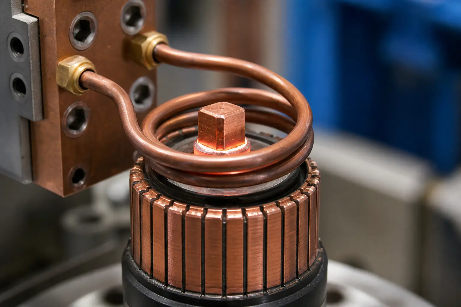
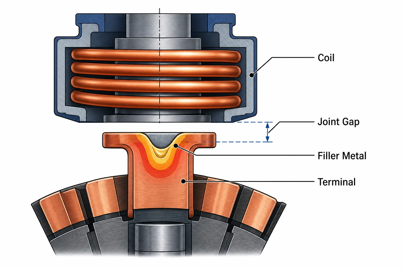
The coil is where the process lives or dies. For motor terminals, the coil typically wraps around the joint zone — either as a split-turn design that allows the commutator to index through, or as a custom-profiled single-turn coil that focuses energy on a specific terminal geometry.
Three rules for terminal brazing coils:
— Coupling gap: Keep the coil-to-joint distance between 1–3 mm. Wider gaps lose efficiency fast; narrower gaps risk arcing if the part or fixture has any runout.
— Heat zone focus: The coil should concentrate flux on the joint interface, not the entire terminal. A coil that heats too broadly will spread the brazing temperature into areas that do not need it, wasting power and potentially damaging insulation.
— Cooling integration: The coil body must carry its own water cooling. In continuous production, a coil without internal cooling will drift out of spec within minutes.
6. Common Defects and How to Fix Them
Most motor terminal brazing defects trace back to one of four root causes. Recognizing the symptom tells you where to look.
| Defect | Likely Cause | Fix |
|---|---|---|
| Incomplete filler flow | Joint did not reach melting temperature | Increase power or heating time; check coil coupling gap |
| Burnt flux residue | Temperature overshoot or excessive heating time | Reduce power; shorten cycle; verify frequency matches joint mass |
| Insulation damage near joint | Heat zone too broad — coil heating beyond the joint | Redesign coil for tighter flux focus; add a heat shield between coil and insulation |
| Joint-to-joint inconsistency | Fixture misalignment, coil gap variation, or cooling drift | Check fixture repeatability; use recipe-based power control; verify cooling water stability |
Key Takeaway
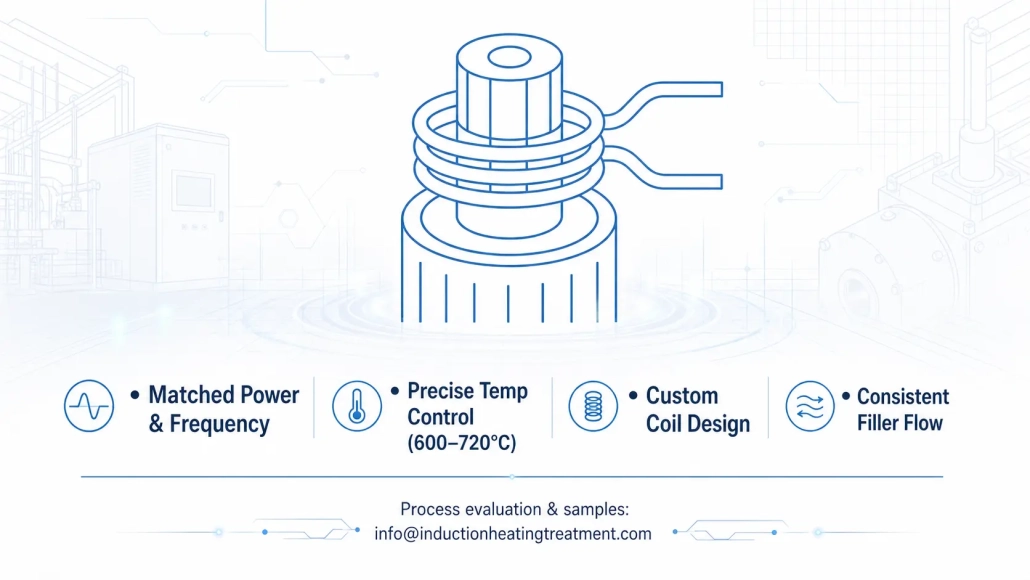
Successful induction heating brazing of motor terminals comes down to matching four things: the right power and frequency for the joint mass, a coil that focuses heat precisely on the braze zone, consistent filler metal placement, and cooling that holds steady across an entire shift. When those four align, induction brazing delivers the speed, repeatability, and joint quality that motor manufacturing demands. When one drifts, the scrap bin fills up fast.
Q: What filler metal is best for motor terminal brazing?
A: For copper-to-copper joints, silver-copper-phosphorus alloys (BCuP series) are preferred — they are self-fluxing on copper and provide good conductivity. For copper-to-brass or high-vibration joints, silver-copper-zinc alloys (BAg series) offer higher strength but require separate flux.
Q: How long does an induction brazing cycle take for a motor terminal?
A: Typically 3–15 seconds of heating time, depending on joint mass and power level. Total cycle time including part loading and unloading ranges from 10–25 seconds for most automated setups.
Q: Can the same coil braze different terminal sizes?
A: A coil designed for one terminal geometry will generally not produce good results on a different size — the coupling gap and flux distribution change too much. Dedicated coils per part family, combined with stored recipes on the power supply, is the standard approach.
Need a Brazing Process for Your Motor Terminals?
Send us your terminal drawings and production volume. We will run a sample brazing trial and recommend a coil and power supply matched to your joint — not a generic quote.