8 Common Induction Hardening Defects and How to Prevent Them
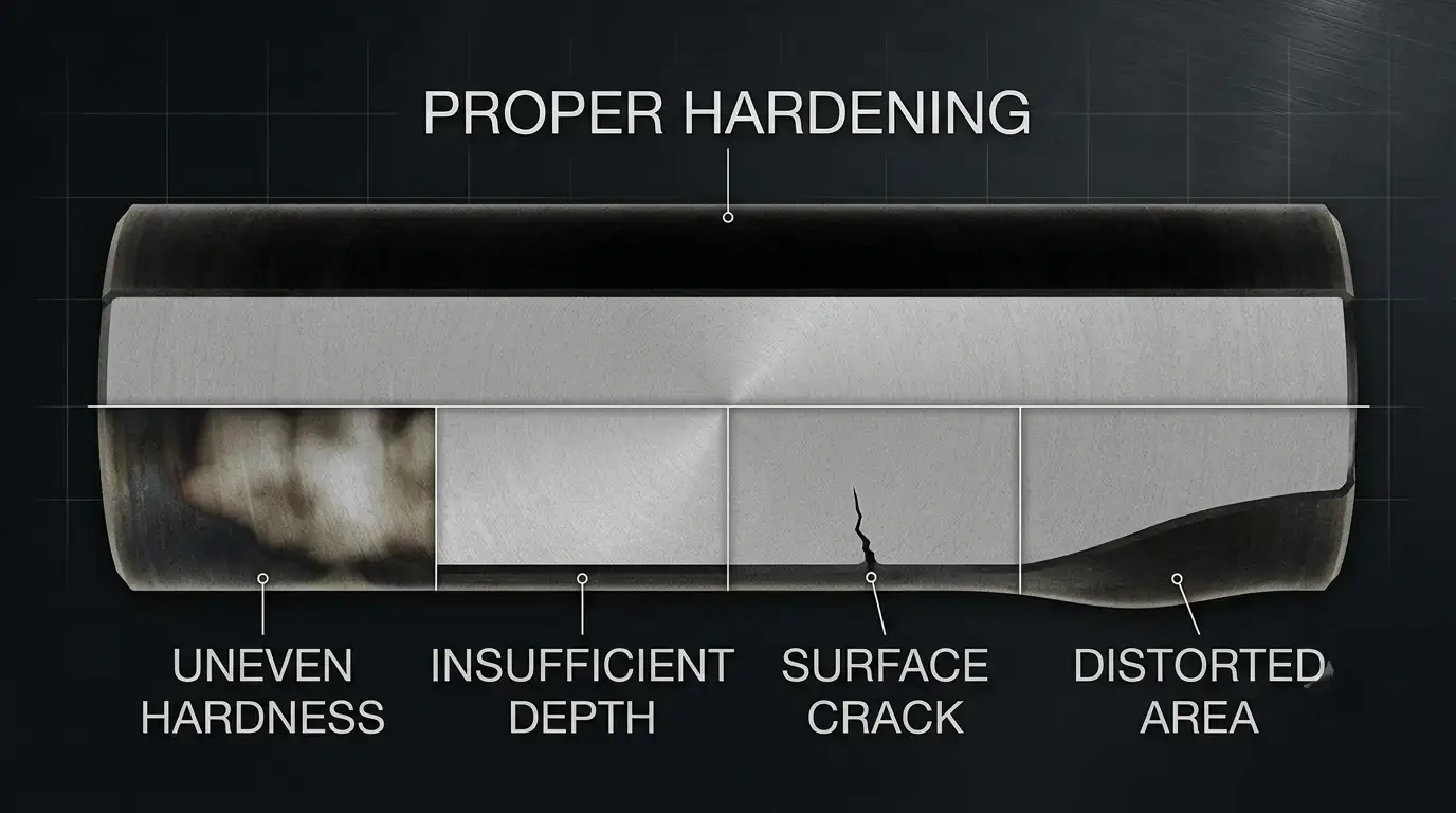
Induction hardening defects are expensive. One cracked or improperly hardened part means scrapped material, lost production time, and customer returns.
Induction hardening delivers fast, localized heating with better energy efficiency than furnace treatment. But consistency depends on seven variables working together: frequency, power density, heating time, coil design, quenching, material properties, and part geometry. When one drifts, defects follow.
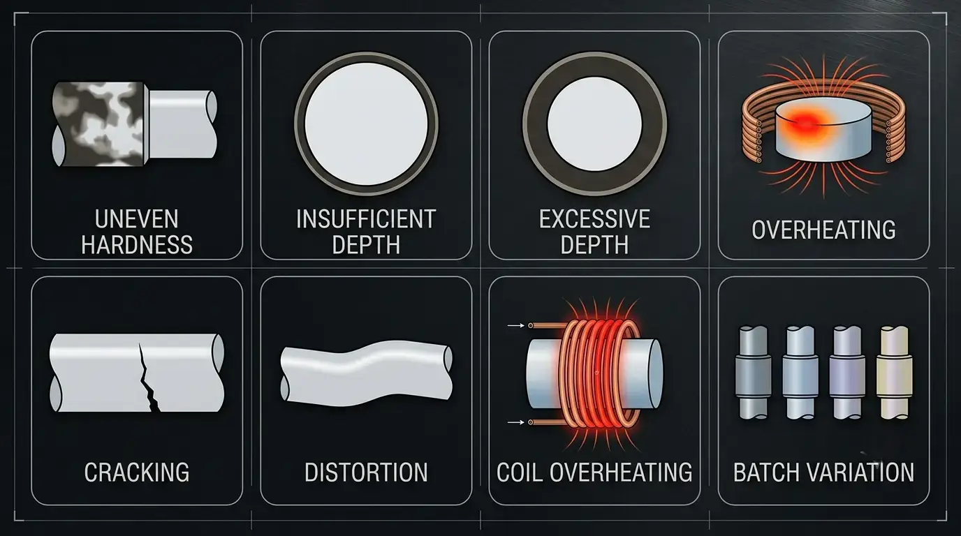
This guide covers eight common induction hardening defects — their root causes, how to prevent them, and how to build a stable process. For application-specific issues, see our guides on bell housing hardening defects and gear hardening defects.
Reader Roadmap
Quality / Process Engineer? Start with Defects 1–4 (Hardness & Depth), then Best Practices.
Maintenance / Operator? Focus on Defect 7 (Coil Overheating) & Defect 5 (Cracking).
Production Manager? Jump to Defect 8 (Batch Variation) & the Quick-Reference Table.
Table of Contents
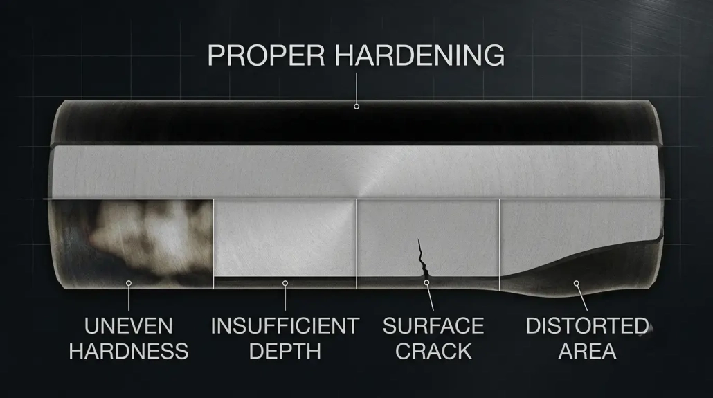
1. Uneven Hardness
The most common induction hardening defect. Some surface areas meet spec — others don’t. The problem often hides until hardness testing or field failure catches it.
| Why It Happens | How to Fix It |
|---|---|
| Coil off-center, creating an uneven magnetic field | Center the coil, maintain a consistent gap |
| Frequency doesn’t match the required heating pattern | Verify frequency matches target depth — frequency guide |
| Inconsistent part positioning between cycles | Use fixtures or automation for repeatable positioning |
| Worn coil — localized wear changes the gap | Schedule regular coil inspection and process checks |
2. Insufficient Case Depth
A shallow hardened case wears fast under load. Critical on gears, bearings, and shafts — where surface stress is high and the hardened layer must survive millions of cycles.
| Why It Happens | How to Fix It |
|---|---|
| Frequency too high — energy stays at the surface | Lower frequency to match target case depth |
| Heating time too short — heat can’t penetrate | Extend heating time or slow scan speed |
| Power too low or scan speed too fast | Pick frequency for depth first, then set power |
| Coil not designed for the target depth | Validate with cross-section during process development |
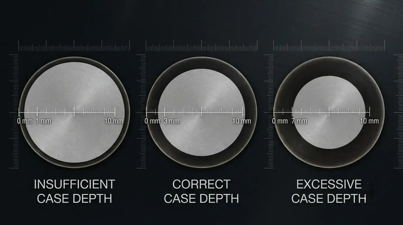
3. Excessive Case Depth
Deeper isn’t better. Excessive depth reduces core toughness, complicates post-hardening machining, wastes energy, and increases distortion risk — all without functional benefit.
| Why It Happens | How to Fix It |
|---|---|
| Frequency too low — energy penetrates deeper than needed | Raise frequency to match required case depth |
| Heating time too long — heat soaks into the core | Reduce heating time to specification |
| Power input beyond what the part requires | Balance frequency, power, and time per part — power selection guide |
4. Surface Overheating
Localized overheating causes grain growth, oxidation, decarburization — or partial melting in severe cases. The part becomes brittle. Hardness readings may still pass.
Why it happens — Power density too high on a small area. Heating cycle too long. Coil design creates magnetic field hot spots. Coil-to-part gap too tight, concentrating energy aggressively.
How to fix it — Match power to part size, not maximum output. Shorten cycle time. Review coil geometry to spread the field evenly. Maintain proper gap and add temperature monitoring (IR sensor or pyrometer).
5. Surface Cracks After Quenching
The most serious induction hardening defect — a cracked part is scrap. Cracks form when thermal and transformation stresses exceed the material’s strength during rapid cooling.
Why it happens — Quench too aggressive for the material grade. High-carbon or high-alloy steel run without parameter adjustment. Overheated before quenching. Sharp corners, keyways, or abrupt section changes concentrating stress during rapid cooling. Inconsistent quench timing.
How to fix it — Treat heating and quenching as one process. Match quench media, concentration, temperature, and flow rate to the material grade. Don’t overheat before quenching. Radius sharp features like corners and splines. For shaft applications, scanning processes are especially sensitive to quench timing.
6. Distortion
Induction hardening causes less distortion than furnace treatment, but dimensional changes still happen — especially on long shafts, thin-walled parts, and asymmetrical geometries. Even small distortion pushes parts out of tolerance.
Why it happens — Uneven heating creates asymmetric thermal expansion. Non-uniform quench — one side cools faster. Asymmetrical part geometry with inherent stress imbalance. Weak fixturing allows the part to move during processing.
How to fix it — Design the coil for uniform heating coverage. Ensure symmetrical quench spray on all sides. Test a sample before full production. Use rigid fixtures that support the part through the entire cycle.
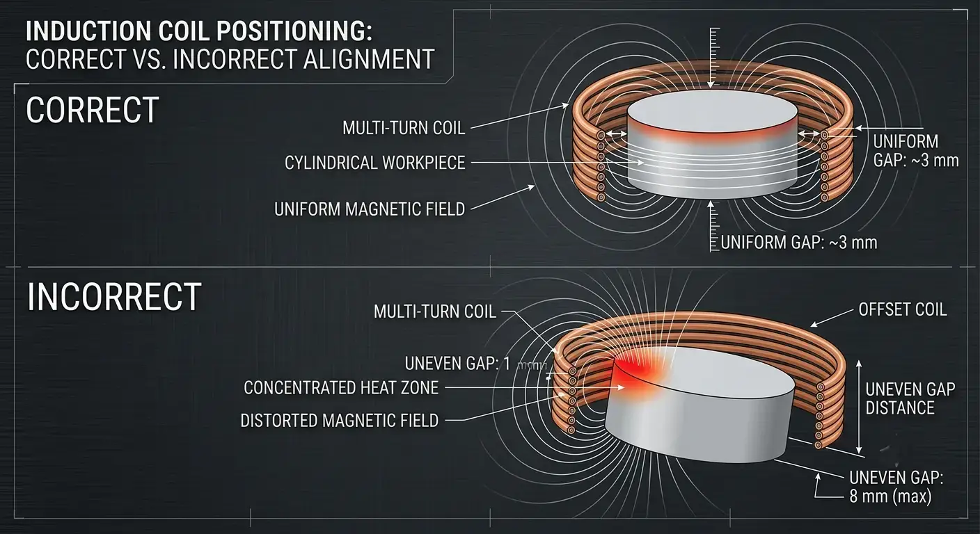
7. Coil Overheating
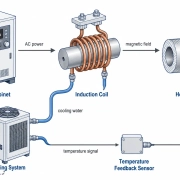
The coil carries high current under constant thermal cycling. A poorly cooled coil degrades fast — and a mid-shift coil failure costs far more than a replacement.
| Why It Happens | How to Fix It |
|---|---|
| Cooling water flow too low or inlet temp too high | Maintain proper flow rate and inlet temperature |
| Blocked or scaled internal channels | Inspect coils regularly for scale and blockage |
| Power exceeds the coil’s thermal design limit | Stay within rated power; cooling system guide |
| Continuous operation beyond rated duty cycle | Respect duty cycle limits; preventive maintenance saves downtime |
8. Inconsistent Results Between Batches
The most frustrating induction hardening defect: every part passes inspection, but hardness and case depth vary batch to batch. Customers notice — even when specs are technically met.
Why it happens — Power supply drifts over time or between shifts. Material variation — different heats or suppliers respond differently. Coil degrades gradually, changing electromagnetic coupling. Operator settings inconsistent on manual equipment. No process monitoring — problems found only at final inspection.
How to fix it — Store heating recipes — don’t rely on operator memory. Monitor power, frequency, time, energy, and cooling in real time. Digital systems with data logging catch drift before it becomes scrap. Validate incoming material, not just outgoing parts.
Best Practices
Seven principles that improve stability across all induction hardening applications:
— Match frequency to depth, not power. Frequency sets the depth. Choose it first. Then set power for cycle time.
— Design the coil for the part. A generic coil that “mostly fits” produces uneven results. The coil is a process tool, not a commodity.
— Keep coil-to-part distance consistent. Small gap changes shift electromagnetic coupling and heating uniformity.
— Cool the coil and the power electronics. An overheating coil distorts heating; overheating electronics cause power drift.
— Verify incoming material. Different heats respond differently. Test a sample from every new supplier or heat.
— Monitor process, not just final hardness. By the time a hardness tester flags a problem, the batch is already bad.
— Validate every new part or process change. One sample run catches problems that cost far less to fix than a batch rejection.
Stable hardening means controlling the whole system — frequency, power, coil, cooling, quench, material, and monitoring — not tweaking one knob.
Quick-Reference: Defects, Causes & Fixes
| Defect | Primary Cause | Key Fix |
|---|---|---|
| 1. Uneven Hardness | Coil misalignment, wrong frequency | Center coil, match frequency to depth, use fixtures |
| 2. Insufficient Depth | Frequency too high, time too short | Lower frequency, extend time, validate cross-section |
| 3. Excessive Depth | Frequency too low, time too long | Raise frequency, reduce time, match spec |
| 4. Overheating | Excessive power density, poor coil design | Reduce power, redesign coil, add temp monitoring |
| 5. Surface Cracks | Overly rapid quench, overheating, stress risers | Adjust quench, control max temp, radius sharp corners |
| 6. Distortion | Uneven heating/quenching, poor fixturing | Uniform coil, symmetrical quench, rigid fixtures |
| 7. Coil Overheating | Insufficient cooling water, blocked channels | Increase flow, inspect for scale, size chiller correctly |
| 8. Batch Variation | Power drift, material variation, no monitoring | Recipe storage, real-time monitoring, material checks |
Key Takeaway
Most induction hardening defects come from the interaction of frequency, power, coil design, time, quench, material, and process control. Fixing one variable in isolation rarely works.
Stable quality starts with the right equipment. Sustaining it takes optimized parameters, reliable cooling, consistent monitoring, and regular validation. Catch root causes early — you reduce scrap, improve repeatability, and extend equipment life.
FAQ
Q: What is the most common induction hardening defect?
A: Uneven hardness. Usually from coil misalignment, wrong frequency, or inconsistent positioning — all preventable with proper setup.
Q: Can increasing power fix insufficient hardening?
A: Not by itself. Power affects speed, but depth depends on frequency, time, and scan speed too. Crank power alone and you risk surface overheating with no depth improvement. Get the frequency-depth match right first — then power sets cycle time. See our power calculation guide.
Q: Why does my induction coil overheat?
A: Low water flow, blocked channels (scale/debris), excessive power, or running beyond duty cycle. Watch coil outlet water temperature — a rising trend means trouble. See our water cooling guide for system-level design.
Q: How do I audit my hardening process?
A: Six checks, under an hour: (1) Verify frequency matches case depth per part number. (2) Inspect coil — gap, wear, water flow. (3) Compare power/time settings to historical baselines. (4) Check quench concentration, temperature, and flow uniformity. (5) Review last 30 days of hardness data — any trend is a warning. (6) Cross-section one part per shift. Catches most issues before they become scrap.
Q: When should I replace vs. repair an induction coil?
A: Replace when: inner wall eroded beyond 10% of original thickness, water flow restricted and chemical cleaning fails, coil body shows cracks or burns, or hardness variation returns right after re-validation. A degraded coil looks usable but silently produces scrap — the replacement pays for itself fast.
Need Help Troubleshooting Your Induction Hardening Process?
Our engineering team can diagnose your specific defects and recommend the right equipment, coil design, and process parameters for your parts.