Máy hàn cảm ứng cho bộ chuyển pha ăng-ten
Ⅰ. Induction Soldering Application Videos
Video 1: Induction Soldering of Phase Shifter Components
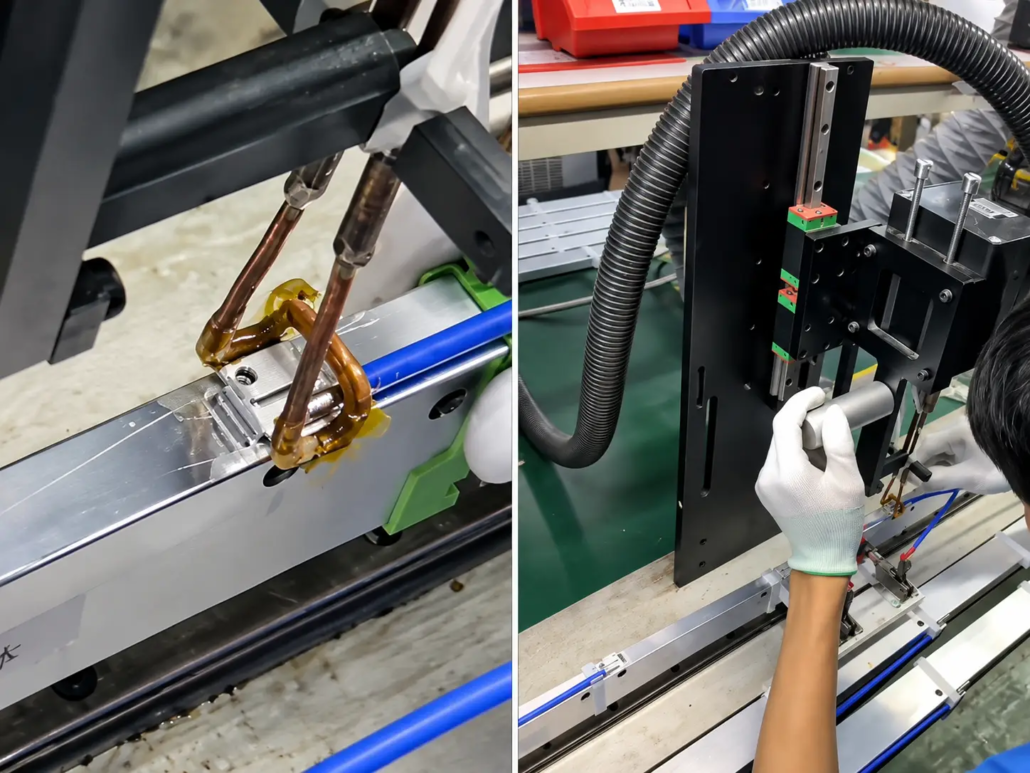
MỘT shaped copper induction coil is positioned close to a metal connection area on the phase shifter assembly. The heating is directed toward the local joint rather than the entire length of the component.
The demonstrated application is identified as using a 6 kW induction heating unit. This is the power rating stated for the video example, not a standard requirement for every phase shifter soldering application.
Video 2: Induction Soldering of Cavity Phase Shifter Wire Connections
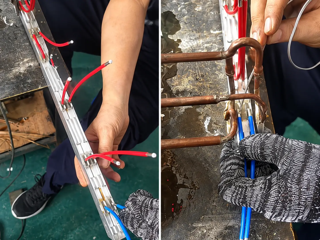
This video shows the soldering of wire connections on an elongated cavity phase shifter. Red and blue connection wires are part of the assembly, and the copper induction coil is positioned near their joining locations.
The coil provides localized heating around the connection area. Its shape and position are selected to accommodate the metal cavity and surrounding components, rather than heating the entire assembly.
Ⅱ. Soldering Applications and Joint Requirements
Phase shifters used in certain base station antennas contain conductive parts that form part of the RF signal path. Tùy thuộc vào thiết kế, soldered connections may be required between wires, terminals and other metal components.
In the two applications shown above, induction soldering is used for selected connection points on the phase shifter assembly. The induction coil is arranged around the available working space so that heating can be applied close to the joint.
Đối với các ứng dụng này, the soldering process must account for several factors:
Joint geometry: The location and accessibility of the connection determine how the induction coil can be positioned.
Component materials: The electrical and thermal properties of the joined metals affect heating behavior.
Soldering requirements: Solder alloy, surface preparation and solder wetting influence joint formation.
Surrounding components: Insulation and other temperature-sensitive materials may limit the allowable heating conditions.
Electrical performance: Connections used in RF assemblies may require additional electrical or RF verification beyond visual inspection.
Induction soldering is most suitable when the joint geometry allows effective heating of the intended metal connection without unacceptable thermal effects on nearby parts.
Ⅲ. Induction Soldering Equipment and Coil Configuration
For antenna phase shifter soldering, the equipment is selected according to the connection geometry and heating requirements rather than the overall size of the component.
The main elements of the soldering setup are the induction power supply, induction coil and workpiece positioning arrangement.
| Equipment Element | Function and Application |
|---|---|
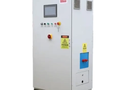
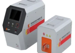
| High-Frequency Induction Power Supply | Provides energy for localized heating. The required output power and operating frequency depend on the joint materials, geometry and soldering conditions. |
| Custom Copper Induction Coil | Shaped to approach the soldering position and provide suitable electromagnetic coupling with the metal connection area. |
| Định vị phôi | Holds or positions the phase shifter so that the relationship between the induction coil and soldering point remains consistent. |
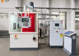
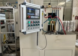
| Production Integration | The induction heating setup can be considered for a dedicated soldering workstation or integration into a larger assembly process, depending on the required equipment configuration. |
Induction Coil Design for Phase Shifter Connections
The two videos show shaped copper induction coils working near specific connection points on elongated metal assemblies. Their geometry allows the heating area to be approached within the available space around the joint.
This is particularly important when soldering positions are close to a cavity wall, adjacent conductors or other structural features.
Coil geometry and clearance influence electromagnetic coupling and heat distribution. A coil suitable for one connection layout may not perform the same way on another phase shifter design.
Vì lý do này, KOTRON evaluates the connection position, surrounding structure and heating requirements when determining an appropriate induction coil arrangement.
Ⅳ. Process Control and Soldering Considerations
During induction soldering, chính từ trường xen kẽ generated by the induction coil produces heating in suitable conductive parts. Heat reaches the joining interface, allowing the solder to melt and wet the prepared surfaces.
Because the induction coil does not need to contact the joint, the process avoids direct heating by a soldering iron tip. Tuy nhiên, heat can still conduct through the connected metal parts, so nearby components must be considered when establishing the heating conditions.
The main process considerations include:
Solder alloy and base materials: The solder melting range and the properties of the joined metals influence the required heating conditions.
Coil positioning: Consistent coil clearance and alignment help maintain repeatable heating at the connection.
Thời gian cấp điện và sưởi ấm: The heating cycle must provide sufficient energy for soldering while avoiding excessive thermal exposure.
Joint preparation: Tình trạng bề mặt, solder placement and flux selection, nếu có thể áp dụng, affect solder wetting and joint formation.
Joint inspection: Completed connections should be evaluated against the relevant mechanical and electrical requirements. RF performance checks may also be necessary for the finished antenna assembly.
Before production, representative soldering trials can be used to assess heating behavior, joint formation and the effect of heat on nearby components.
Ⅴ. Custom Induction Soldering Solutions and Inquiry
KOTRON offers application-oriented induction soldering equipment for antenna phase shifters and related telecommunications components.
The equipment configuration can be evaluated according to the customer’s actual soldering locations, component materials and production requirements.
To discuss an induction soldering application, vui lòng cung cấp:
— Photos or drawings of the phase shifter assembly.
— The location and number of soldering points.
— Materials and dimensions of the components being joined.
— Wire sizes and connection details, nếu có thể áp dụng.
— Solder alloy and flux information, nếu có.
— Required production capacity and workpiece handling method.
— Any temperature limitations or joint inspection requirements.
These details help determine the suitability of induction soldering and support the selection of the power supply, coil geometry and equipment arrangement.
Looking for an induction soldering machine for antenna phase shifters or similar RF component connections?
Contact KOTRON with your workpiece details to discuss a suitable induction soldering solution.
Ⅵ. Câu hỏi thường gặp (Câu hỏi thường gặp)
Bấm vào một câu hỏi để mở rộng câu trả lời.
Can induction soldering be used for wire connections on cavity phase shifters?
Có. Induction soldering can be used for suitable wire connections on cavity phase shifters, as demonstrated in the application video above. The induction coil is positioned near the joining area to heat the metal connection. Suitability depends on the wire and terminal materials, hình học chung, solder alloy and surrounding components.
What power is required for an antenna phase shifter induction soldering machine?
The required power depends on the materials, joint size, induction coil design and heating requirements. One of the applications shown above uses a 6 kW induction heating unit, but this does not mean every phase shifter requires the same power rating. Equipment selection should be based on the actual soldering application.
Can induction soldering damage nearby wires or sensitive components?
Although the induction coil does not need to touch the solder joint, heat can still travel through the connected metal parts. Nearby wire insulation and temperature-sensitive components must therefore be considered when selecting coil geometry, power and heating time. Representative soldering trials can help evaluate the thermal effects.
Can the induction soldering equipment be customized for different phase shifter designs?
Có. The induction coil and equipment arrangement can be adapted to different connection positions and workpiece geometries. Customers can provide component drawings or photos, joint details, material information and production requirements so KOTRON can evaluate a suitable soldering setup.