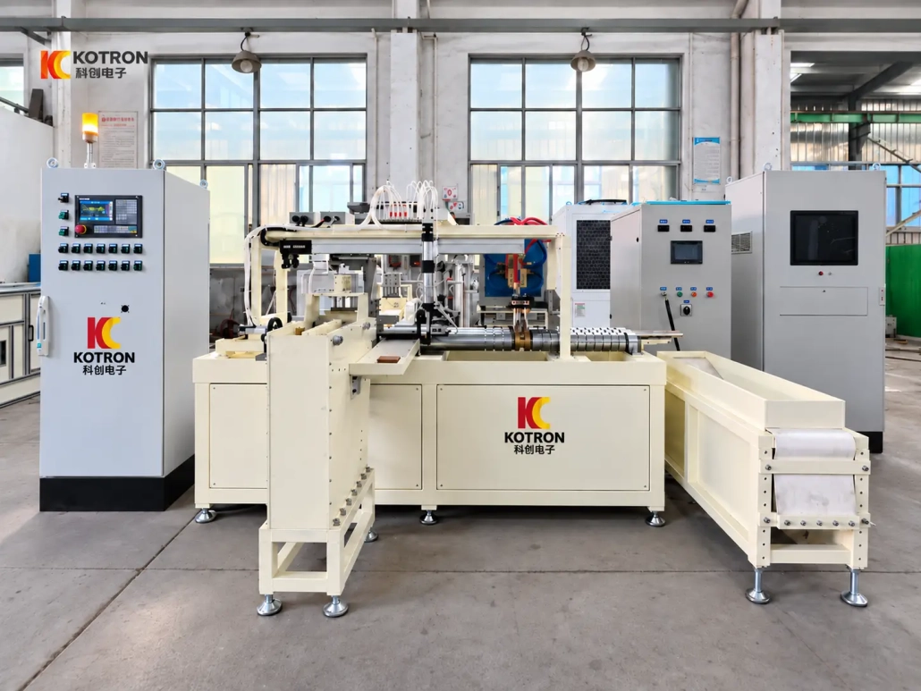
Automatic Induction Hardening Line for Pins and Bushings
Ⅰ. See the Automatic Hardening Line in Operation
The video shows workpieces moving through an automatic induction hardening process, including feeding, transfer between positions, heating, quenching and final discharge.
For batch production, heating is only one part of the job. Each component also has to reach the correct position, complete the programmed process and leave the working area before the next cycle begins.
This is where an automatic line differs from a manually loaded standalone pin induction hardening machine. Workpiece handling and heat treatment are coordinated as one repeated production process.
Ⅱ. Pins, Bushings and Suitable Workpieces
The line is mainly intended for cylindrical components requiring surface or localized hardening.
Typical workpieces include:
•Pins
•Bushings
•Pin shafts
•Pivot pins
•Sleeve-type components
•Similar cylindrical mechanical parts
Pins and bushings should not automatically be treated as the same heating job.
A solid pin and a hollow bushing can have different section thicknesses, heat flow, support requirements and hardening zones. Even two pins with similar outside diameters may need different processes because of differences in material, hardening length or required case depth.
For bushings, bore dimensions, wall thickness and the required hardened area also need to be considered before the inductor and fixture are designed.
The most useful information for equipment selection includes:
•Material and grade
•Outside diameter
•Inside diameter for bushings
•Overall length
•Required hardening area
•Target surface hardness
•Effective case depth
•Required production rate
The actual workpiece should therefore come before the machine model or power rating.
Ⅲ. How the Automatic Induction Hardening Line Works
A typical production sequence is:
Loading → Feeding → Positioning → Induction Heating → Quenching → Transfer → Discharge
The exact sequence can be adjusted for the workpiece.
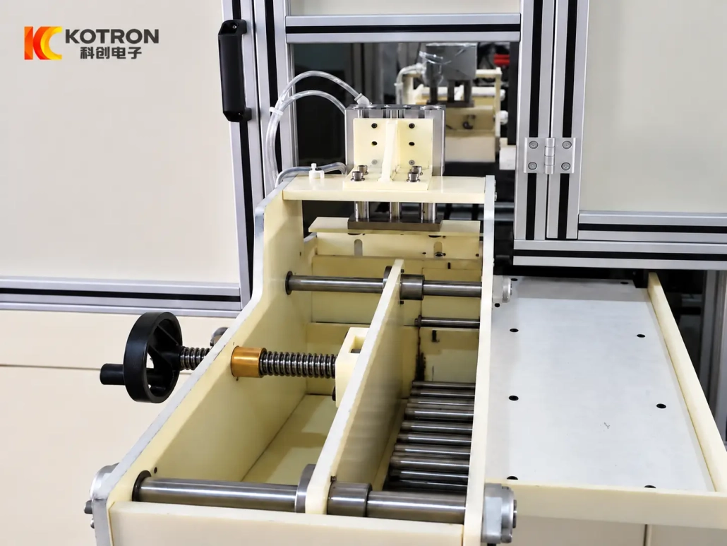
At the loading section, cylindrical components enter the feeding mechanism and move forward in a controlled sequence. Mechanical pushing, rolling, tilting or other transfer methods can be selected according to the size, orientation and handling characteristics of the part.
Once the workpiece reaches the processing position, the machine locates it according to the programmed cycle. The induction system then supplies the required heating energy through the inductor.
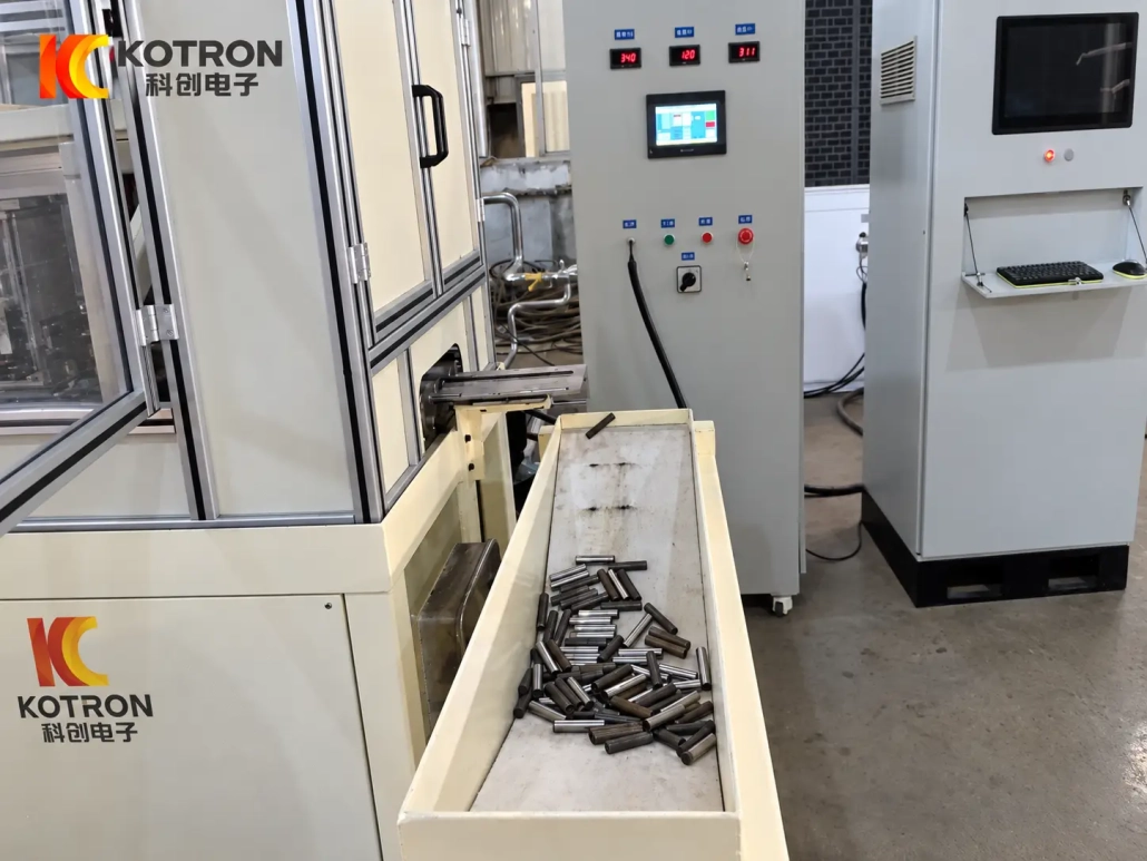
After heating, the required area is quenched. The workpiece is transferred away from the processing position and discharged, allowing the next part to enter the cycle.
Depending on the hardening requirement, the workpiece may remain stationary or move relative to the inductor. The final motion and quenching method are selected according to the required hardened pattern rather than a fixed machine template.
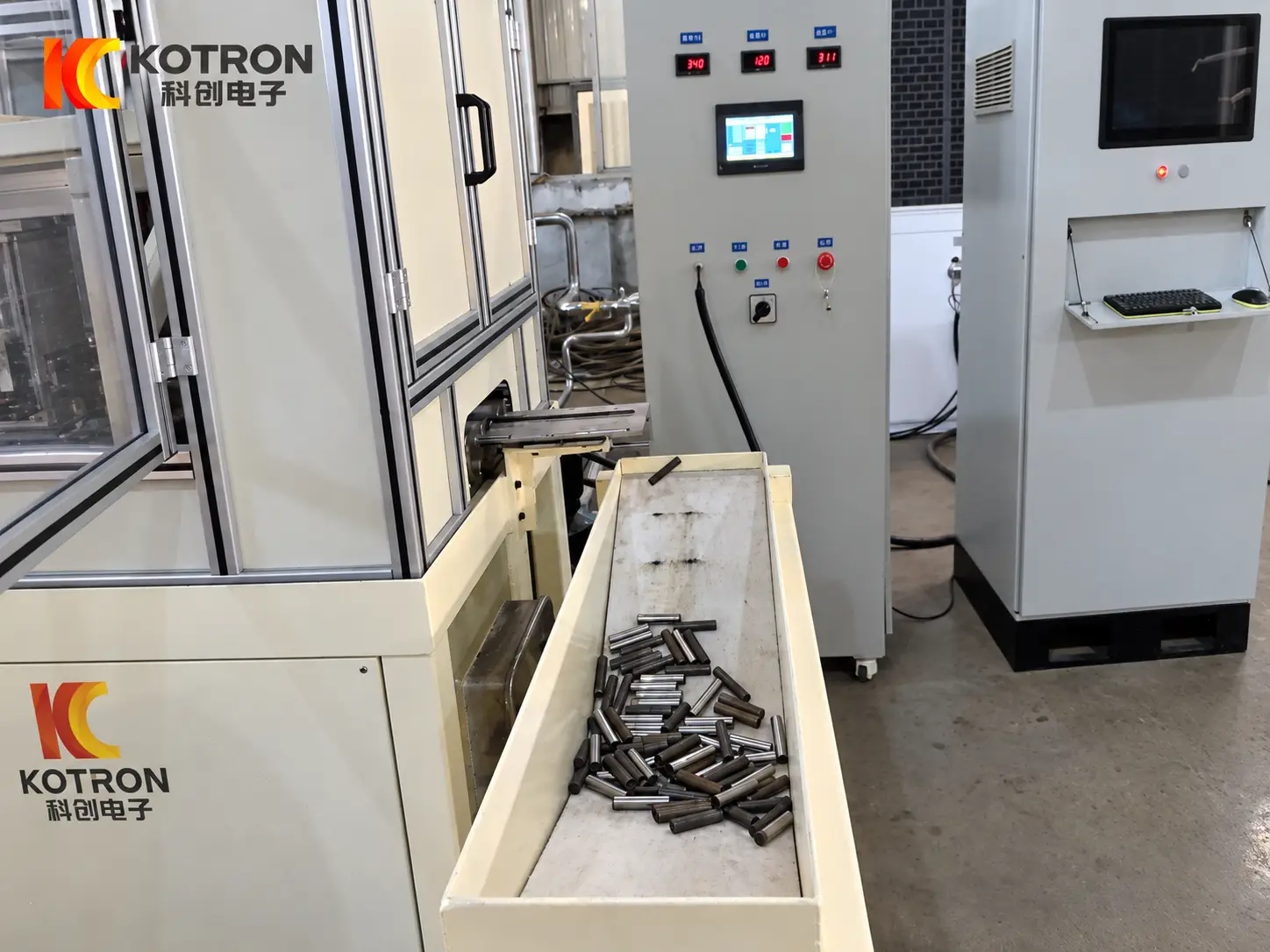
The discharge section completes the automatic cycle by moving processed parts away from the hardening station without requiring manual unloading after every cycle.
Ⅳ. Hardening Process for Pins and Bushings
A pin induction hardening machine should not be selected from rated power alone.
The final hardening result is influenced by several process variables working together:
Power + Frequency + Inductor Design + Heating Time + Workpiece Motion + Quenching
The material and geometry of the workpiece determine how these variables should be combined.
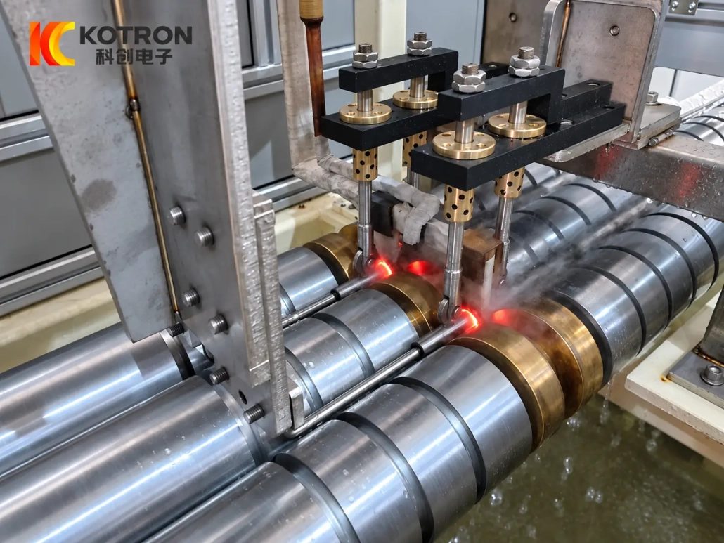
The inductor is especially important. Its shape and relationship to the workpiece determine where electromagnetic energy is concentrated. A short local hardening zone, a longer cylindrical surface and a bushing with a different wall thickness may require different coil arrangements.
Frequency must also suit the application. A higher or lower frequency is not automatically better; it has to be selected together with the workpiece dimensions and required heating depth.
Heating time, power level and movement then need to work with the quenching stage. Changing one variable can alter the temperature distribution and hardened pattern.
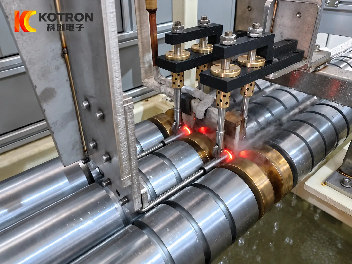
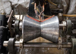
This process image shows the actual relationship between the workpiece, inductor and heated area during production.
For equipment selection, we normally evaluate:
•Material and grade
•Workpiece dimensions
•Hardening area
•Required surface hardness
•Effective case depth
•Hardening length
•Production cycle
The aim is not simply to heat the part quickly. The process has to produce the required hardened zone repeatedly under production conditions.
Ⅴ. Automatic Feeding and Line Configuration
For batch production, workpiece handling has a direct effect on how practical the line is to operate.
Cylindrical components need to be separated, transferred and positioned without interrupting the production sequence. Depending on the workpiece, this can be achieved with relatively simple mechanical mechanisms or with a more advanced automatic handling system.
Possible configurations include:
•Mechanical pushing
•Roller transfer
•Tilting transfer
•Pneumatic movement
•Servo positioning
•Position sensors
•Customized fixtures
•Automatic loading and unloading interfaces
The most suitable solution is not necessarily the most complicated one.
For a straightforward cylindrical part, a mechanical pushing and transfer arrangement may be more suitable than adding unnecessary robotic handling. A larger integrated line may require servo axes, additional sensors or communication with upstream and downstream equipment.
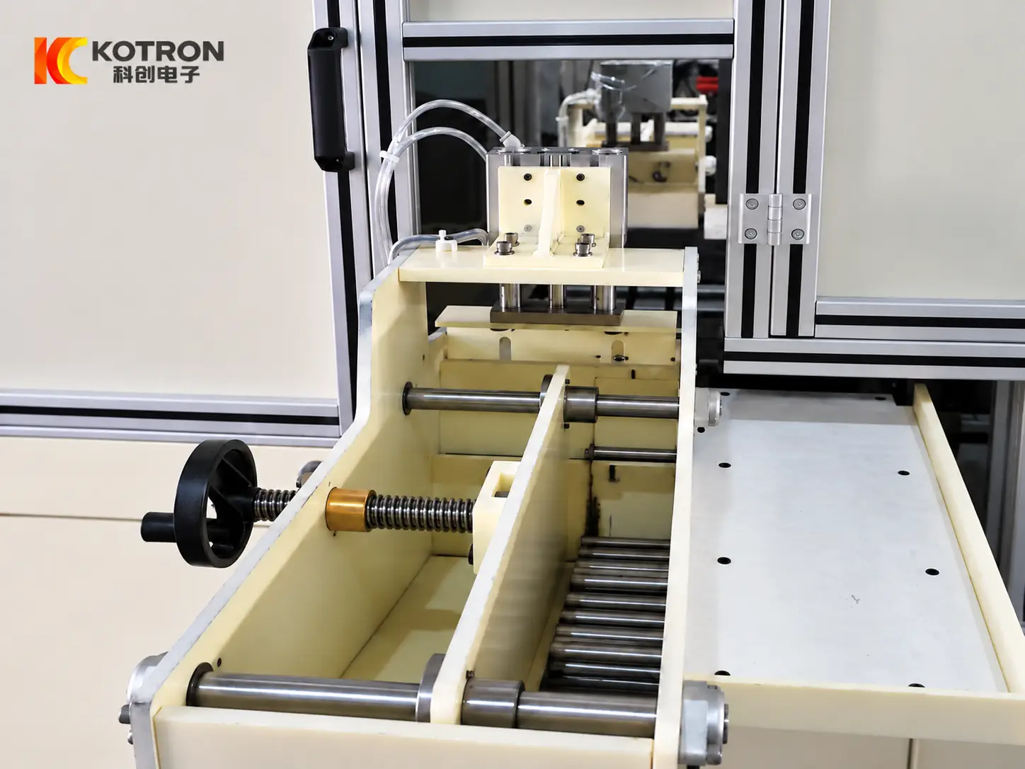
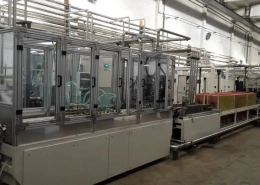
A complete line can typically be divided into several functional sections:
| System | Main Function |
|---|---|
| Feeding system | Introduces workpieces into the production sequence |
| Transfer mechanism | Moves parts between positions |
| Positioning / fixture system | Locates the workpiece for processing |
| Induction heating station | Heats the required area |
| Quenching system | Cools the heated zone according to the process |
| Automatic discharge | Transfers processed parts out of the line |
| Control system | Coordinates the electrical and mechanical sequence |
The layout can be customized according to workpiece orientation, available factory space and connection with existing production equipment.
Ⅵ. IGBT Power, DSP Control and PLC Automation
The electrical and automation system can be configured according to the required process and production level.
IGBT-Based Induction Power Supply
The IGBT power supply provides the heating power required for induction processing. Power rating and operating frequency are selected according to the workpiece, hardening requirement and production cycle.
DSP Digital Control
DSP control is used for digital regulation and monitoring of the induction power supply. Depending on the configuration, parameters such as current, voltage, power, frequency and heating time can be monitored or incorporated into the process program.
PLC Sequence Control
The PLC coordinates feeding, positioning, heating, quenching, transfer and discharge. An HMI can provide parameter setting, operating status and alarm information.
Where required, the control system can also be customized with workpiece recipes, sensors, servo control, data recording and communication with upstream or downstream equipment.
Ⅶ. Configured Around Your Workpiece and Production Requirement
There is no useful universal specification for every pin and bushing hardening line.
A small pin produced continuously in large batches and a larger pin processed at a lower production rate may both require induction hardening, but their feeding systems, power supplies, fixtures, inductors and processing cycles can be very different.
The same applies to bushings.
Rather than selecting the equipment only from a model number or power rating, we recommend starting with the workpiece and the required heat-treatment result.
Please provide the following information where available:
Workpiece Information
• Part drawing
• Part type
• Material and grade
• Outside diameter
• Inside diameter for bushings
• Length
• Weight
Heat-Treatment Requirement
• Hardening area
• Required surface hardness
• Effective case depth
• Hardening length
• Local or continuous hardening requirement
Production Requirement
• Required output
• Current loading method
• Required automation level
• Available installation space
• Existing upstream or downstream equipment
• Data-recording or traceability requirements
From this information, the project can be configured around the appropriate induction power, operating frequency, inductor, quenching arrangement, feeding method, positioning mechanism and automation system.
Customers do not need to determine every electrical or mechanical detail before contacting us. A clear workpiece drawing and heat-treatment requirement are usually a better starting point than simply specifying a certain kilowatt rating.
Ⅷ. Frequently Asked Questions
Click a question to expand the answer.
Can the same line process both pins and bushings?
A line can be designed around a suitable family of pins and bushings. Different workpieces may require different inductors, fixtures, positioning components or process recipes, so the practical range should be confirmed from the actual drawings.
Can one line process several workpiece sizes?
Yes, within the mechanical and electrical capacity of the equipment. Depending on the size difference, changeover may involve adjustment or replacement of the inductor, fixture or positioning components together with a different process program.
Can only a selected area of the workpiece be hardened?
Yes. Induction heating is suitable for localized heat treatment. The required hardening zone should be clearly marked on the drawing so that the inductor, workpiece movement and quenching arrangement can be evaluated together.
Can the line be connected to existing production equipment?
Yes. Feeding, discharge, mechanical interfaces and control communication can be customized after the existing production flow and factory layout are reviewed.
What information is required for a quotation?
The most useful starting information is workpiece drawing, material, dimensions, hardening area, surface hardness, effective case depth and required output. Photos or videos of the existing production process are also useful when the new equipment needs to connect with an existing line.