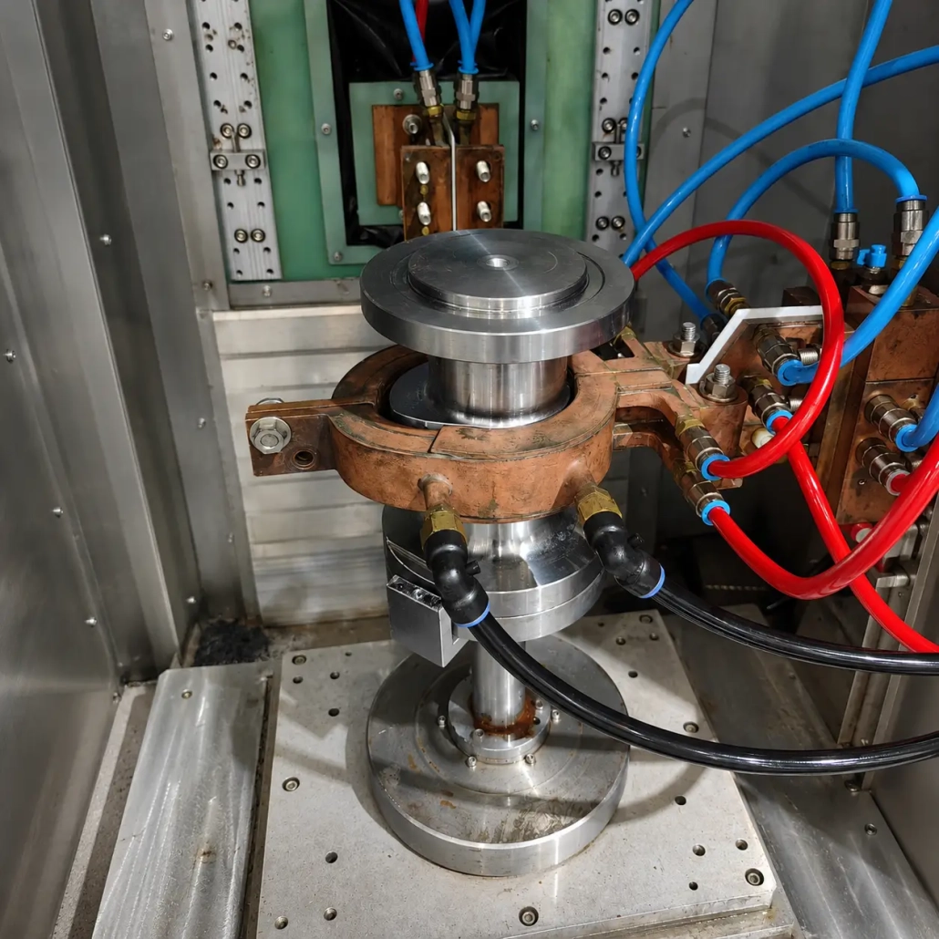
Cam Lobe Induction Hardening Machine
Ⅰ. Cam Lobe Hardening in Operation
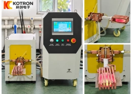
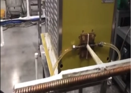
The individual cam lobe is positioned inside a dedicated induction coil and heated along the required working surface.
The exact heating sequence depends on the lobe geometry, material and hardening requirement. The fixture, inductor and quenching arrangement are designed as one process rather than selected separately.
This is particularly important for profiled parts where the distance between the workpiece surface and the induction coil changes around the perimeter.
Ⅱ. Why Cam Lobes Need a Profiled Inductor
A cam lobe is not a circular workpiece.
Its profile includes the cam nose, flanks and base-circle region, and the radius changes continuously around the working surface.
Because of this changing profile, the coupling gap between the cam surface and the inductor also changes. A conventional circular induction coil is therefore not always suitable.
The inductor needs to follow the workpiece geometry closely enough to control the heating pattern around the required surface.
A customized cam lobe inductor can be developed around:
— Cam profile
— Coil-to-workpiece spacing
— Required hardened area
— Available space around the fixture
— Heating and quenching arrangement
The coil shape is therefore determined from the actual workpiece rather than from the nominal outside diameter alone.
Ⅲ. Customized Coil and Hardening Setup
The induction coil is only one part of the cam lobe hardening setup.
The workpiece also needs to be positioned consistently relative to the inductor. For separate cam lobes, the bore and side faces can be used as references when developing the fixture, depending on the actual part geometry.
The heating zone should correspond to the working surface that requires hardening. Areas that do not need treatment should not simply be heated because they are close to the coil.
For this reason, we develop the inductor and fixture around the actual part drawing and hardened-zone requirement.
Different cam profiles may require different tooling even when the overall part dimensions are similar.
Ⅳ. Machine Configuration
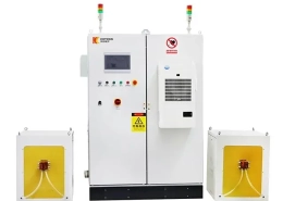
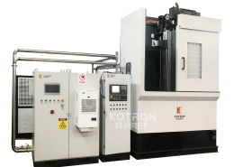
A cam lobe induction hardening system can include:
• Workpiece positioning fixture
• Customized induction inductor
• Induction heating power supply
• Machine movement mechanism
• Quenching and cooling arrangement
• Electrical control system
The mechanical layout is selected according to how the cam lobe is loaded, positioned, heated and removed.
For higher production requirements, the handling and station arrangement can also be developed around the required production cycle.
Ⅴ. What Determines the Hardening Process?
There is no single power setting, frequency or coil design suitable for every cam lobe. Several workpiece conditions need to be considered together.
| Workpiece factor | What it determines |
|---|---|
| Cam profile | Inductor shape and the coupling gap around the workpiece |
| Material | The induction heating and hardening process |
| Required hardened zone | Which part of the outer profile is hardened |
| Hardness and case depth | Process requirements to fix before equipment selection |
| Production rate | Fixture, loading method and overall machine arrangement |
A technically useful proposal therefore starts from the workpiece and its heat-treatment requirement, not from machine power alone.
Ⅵ. Send Us Your Cam Lobe Drawing
For a cam lobe hardening project, please provide:
• Cam lobe drawing
• Material and grade
• Outer profile and dimensions
• Bore diameter
• Workpiece width
• Required hardened area
• Target hardness
• Effective case depth
• Required production rate
If possible, mark the required hardened area directly on the drawing.
From this information, we can evaluate the induction coil, fixture, heating process, quenching arrangement and machine configuration together.
This page focuses on separate cam lobe pieces. If your workpiece is a complete camshaft with the lobes already integrated or assembled on the shaft, see our Camshaft Induction Hardening Machine instead.
Frequently Asked Questions
Click a question to expand the answer.
Is this machine for separate cam lobes or complete camshafts?
This page covers separate cam lobe pieces. If the lobes are already integrated or assembled on a complete shaft, see our Camshaft Induction Hardening Machine.
Why can’t a standard circular coil be used?
A cam lobe has a continuously changing profile — cam nose, flanks and base-circle region. The coupling gap between the workpiece and the coil changes around the perimeter, so a circular coil cannot follow the geometry. A profiled inductor is developed to match the actual lobe profile.
What do I need to provide for a technical proposal?
The cam lobe drawing (with the required hardened area marked, if possible), material and grade, outer profile and dimensions, bore diameter, workpiece width, target hardness, effective case depth and required production rate.
How is a separate cam lobe positioned during heating?
The bore and side faces can be used as reference surfaces when developing the fixture, so the workpiece is positioned consistently relative to the inductor. The exact approach depends on the actual part geometry.
Can one inductor handle different cam profiles?
Not always. Different cam profiles may require different tooling even when the overall dimensions are similar, because the coil shape is determined from the actual workpiece rather than the nominal outside diameter alone.
Send Us Your Cam Lobe Drawing
Provide your cam lobe drawing and requirements, and we will evaluate the induction coil, fixture, heating process and machine configuration together.