
HF Induction Welding for Tube & Pipe: How It Works and What Affects Weld Quality
HF induction welding is widely used to produce longitudinally welded steel tube and pipe. From the outside, the process looks straightforward: form a strip into a tube, heat the two edges and squeeze them together.
The actual welding zone is much less simple.
The HF power supply is one part of a system that also includes strip forming, the induction coil, the weld Vee, the impeder, squeeze rolls and the continuously moving tube. Changes in any of these can alter where the current flows, how the edges heat and what happens at the weld point.
This is one reason a weld problem should not automatically be treated as a power-supply problem. HF tube welding is an electromagnetic, thermal and mechanical process working at the same time.
| 1. How HF Welding Works | 5. Power, Frequency & Line Speed |
| 2. Current Concentration | 6. More Heat ≠ Better Welding |
| 3. The Weld Vee | 7. Why Welds Become Unstable |
| 4. The Impeder | 8. A Stable Process |
1. How HF Induction Tube Welding Works
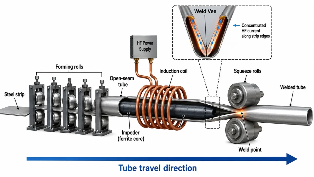
Production normally starts with steel strip passing through a series of forming rolls. The rolls progressively bend the strip until it approaches a round or other required tube profile, while a narrow opening remains between the two strip edges.
Near the welding station, these open edges form what is usually called the weld Vee.
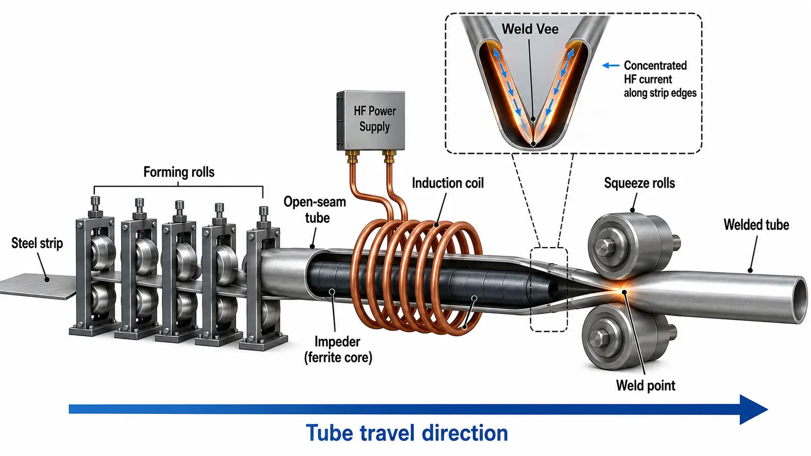
A high-frequency alternating current is supplied to an induction coil positioned around the tube ahead of the weld point. The electromagnetic field from the coil induces current in the conductive strip. The useful part of this current travels along the edges toward the point where they meet.
Electrical resistance in these narrow current paths produces rapid heating.
Once the edges reach the required welding condition, squeeze rolls force them together. The heated edges are mechanically joined, creating the longitudinal weld seam as the tube continues through the mill.
So the process can be viewed as two closely connected stages: electromagnetic edge heating → mechanical joining.
The heating zone is very localized compared with the overall tube size. That localization is one of the characteristics that allows HF welding to operate continuously at high production speeds.
2. Why Current Concentration Matters
Putting an induction coil around a formed tube does not mean that all induced current contributes equally to welding.
Current can follow different paths through the strip. Some travels toward the weld point along the open edges, while some can flow in less useful directions around the tube.
For welding efficiency, the aim is to concentrate as much useful current as possible along the strip edges downstream of the coil and toward the weld point.
At high frequency, current penetration into the material is relatively shallow. The close spacing of the two edges near the Vee also affects current concentration. As the edges approach each other, the electromagnetic conditions change continuously until they meet.
This explains why a tube mill can have adequate HF power but still show poor or unstable heating if the welding geometry is wrong.
Power reaches the machine electrically. The weld setup determines how effectively that power is used at the strip edges.
3. The Weld Vee Is More Important Than It Looks
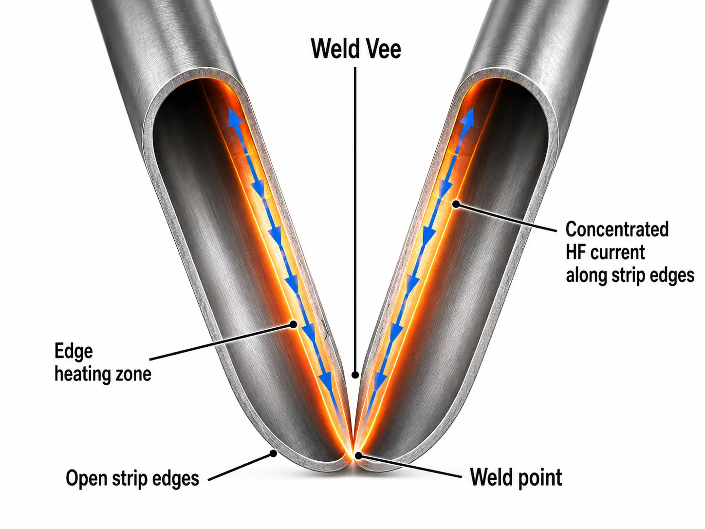
The V-shaped opening just ahead of the weld point may appear to be a simple result of tube forming. In HF welding, its geometry directly affects the heating process.
The Vee is created as the formed strip edges gradually approach one another. Its angle, length and stability influence current distribution and therefore the temperature developed along the edges.
Forming conditions matter here. Spring-back after the strip leaves the forming rolls can distort the expected Vee geometry. Edge alignment can also change as mill settings, strip condition or roll setup change.
A 2024 three-dimensional simulation study of HF induction tube welding found that both Vee geometry and spring-back influence current distribution. In the specific cases modeled by the researchers, increasing the Vee angle also increased the width of the heat-affected zone. Those numerical values are specific to the simulated tube dimensions and should not be treated as a universal setup rule.
The practical point is more useful than a fixed angle: a stable weld requires a stable Vee.
If the Vee moves or changes shape during production, changing HF power alone may compensate for the symptom without correcting the cause.
4. What Does the Impeder Actually Do?
Inside the formed tube, close to the welding area, there is usually an impeder containing high-permeability magnetic material.
Its job is not to heat the tube directly.
The impeder guides magnetic flux and discourages induced current from taking an easier path around the inside circumference of the tube. This helps direct more useful current toward the open strip edges and the weld point.
Without an effective impeder, more leakage current can circulate through unwanted paths. That consumes power and produces heating where it is not needed. Numerical analysis also shows that the distance between the impeder and the inside surface can influence the temperature distribution across the strip edge.
This makes impeder condition and positioning part of the welding setup, not simply a maintenance detail.
The relative positions of the coil, impeder, strip edges and weld point need to work together.
When weld performance gradually deteriorates, checking only generator output can miss a worn, damaged or incorrectly positioned part of the welding system.
5. Power, Frequency and Line Speed Work Together
One of the easiest mistakes in HF tube welding is to discuss welding power as an independent number.
It is not.
The amount of energy delivered to a given section of strip depends partly on how quickly that section passes through the heating zone. Increase the line speed without an appropriate change in heating conditions and there is less time available to bring the edges to the required welding state.
This relationship is sometimes expressed through a heat-input factor based on welding power relative to line speed. Research on HFI welded pipe has shown that heat input and squeeze force can affect the resulting mechanical properties of the welded region.
Tube diameter and wall thickness also matter. A setup developed for a thin-wall tube cannot simply be transferred to a heavier-wall product while keeping every electrical parameter unchanged.
Frequency adds another variable. It affects current penetration and temperature distribution and can influence the shape and width of the heated zone. Research models have shown changes in HAZ width when welding frequency changes, although the exact response depends on tube dimensions and the rest of the setup.
In production, these variables have to be considered together: tube size + wall thickness + material + line speed + frequency + power + weld geometry.
There is no useful rule that says more HF power automatically produces a better weld.
6. More Heat Does Not Automatically Mean Better Welding
The purpose of HF induction welding is to create the correct thermal and mechanical conditions at the edges when they reach the squeeze point.
Too little heat can prevent proper joining. Simply adding power, however, is not a complete solution.
Excessive or poorly distributed heat changes the thermal profile around the weld and can enlarge the affected region. At the same time, the squeeze rolls must apply the required mechanical action while the edges are in the appropriate condition.
This interaction is why looking only at generator readings gives an incomplete picture of weld quality.
A useful diagnosis starts with the process itself. Is the line speed stable? Is the Vee behaving consistently? Are the edges aligned? Is the impeder in the correct position and condition? Has the coil position changed? Are the squeeze rolls set correctly?
A power adjustment may be necessary, but it should be made with those conditions in mind.
7. Why HF Weld Quality Can Become Unstable
When a tube mill runs well for hours and then starts producing an inconsistent weld, the cause may be somewhere outside the HF generator.
Small changes in strip forming can shift the Vee. A damaged or incorrectly located impeder changes magnetic conditions inside the tube. Coil position affects electromagnetic coupling. Changes in line speed alter the heat input received by each section of material.
Mechanical conditions at the squeeze rolls add another layer.
These factors interact. A forming problem may first appear to the operator as a heating problem because the current path has changed. Increasing power may temporarily improve the appearance of the weld while leaving the underlying geometry unchanged.
This is what makes HF induction welding different from treating the welder as a standalone heat source.
The welding line is a system.
Modern numerical studies describe HFI welding as a multi-physics process involving electromagnetic heating, heat transfer, mechanical joining and metallurgical changes in a continuously moving tube.
8. A Stable Weld Comes From a Stable Process
Several individually reasonable settings can still produce a poor result if they do not work together.
HF induction welding makes high-speed continuous tube production possible by concentrating heat in a very small region immediately before the strip edges are joined.
But the HF generator cannot create a good weld by itself.
Current path, Vee geometry, impeder condition, coil position, frequency, power, line speed, forming stability and squeeze-roll setup all influence what happens in the few moments before the edges become a welded seam.
When troubleshooting or optimizing an HF tube mill, looking at those relationships is usually more useful than asking one question such as “Do we need more power?”
The better question is: Are the electrical, thermal and mechanical parts of the welding process working in the same window?
Frequently Asked Questions
Do I need more power if the weld becomes unstable?
Not necessarily. Check the Vee geometry, edge alignment, impeder position and line speed first. A forming or impeder problem often shows up as a heating problem, and adding power only masks the symptom without correcting the cause.
Can I use the same settings for different tube sizes?
No. Tube diameter and wall thickness change the required frequency, power and line speed. A setup developed for thin-wall tube cannot be transferred to a heavier-wall product while keeping every electrical parameter unchanged.
Why does the impeder matter if it does not heat the tube?
It guides magnetic flux and discourages induced current from circulating around the inside of the tube. Without an effective impeder, more current takes an unwanted path, consuming power and producing heating where it is not needed.
What should I check when weld quality gradually deteriorates?
Check whether the Vee is stable, the edges are aligned, the impeder is in position and undamaged, the coil position has not changed, and the squeeze rolls are set correctly.
Need the Right HF Setup for Your Tube Mill?
Welding power, frequency, coil design and line speed all have to match your tube size and material. Tell us what you are producing and we will help specify the equipment.


