
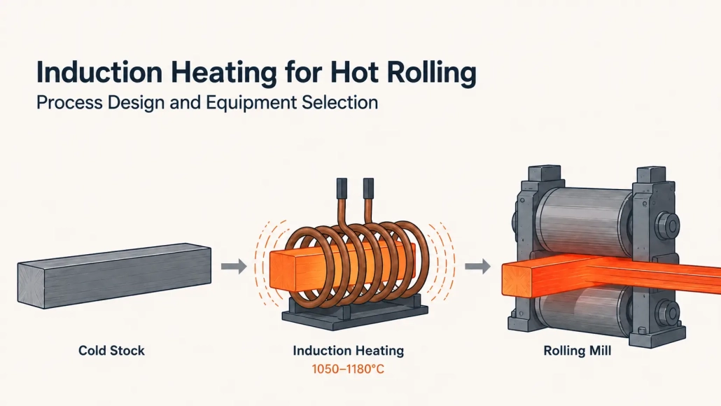
Induction Heating for Hot Rolling: Process Design and Equipment Selection
A hot rolling mill producing 500,000 tonnes per year loses roughly 7,500 to 15,000 tonnes of steel to scale before the first reduction pass — metal that was purchased, heated, and never turned into product. Induction hot rolling drops that number below 0.5%. Startup takes under a minute instead of half a shift. The energy goes into the workpiece, not into heating a furnace cavity the size of a bus.
Fitting induction into a rolling line means matching material grade, cross-section, line speed, and temperature measurement to a heating system that holds consistent temperature at the mill entry — not just at the heater exit. This guide covers where induction fits in the hot rolling process, what controls heating quality, and what a supplier needs to size the system correctly.
| 1. Where Induction Fits in Hot Rolling | 2. Four Variables That Control Heating Quality |
| 3. When Induction Wins — and When It Doesn’t | 4. How to Specify a System |
1. Where Induction Fits in Hot Rolling
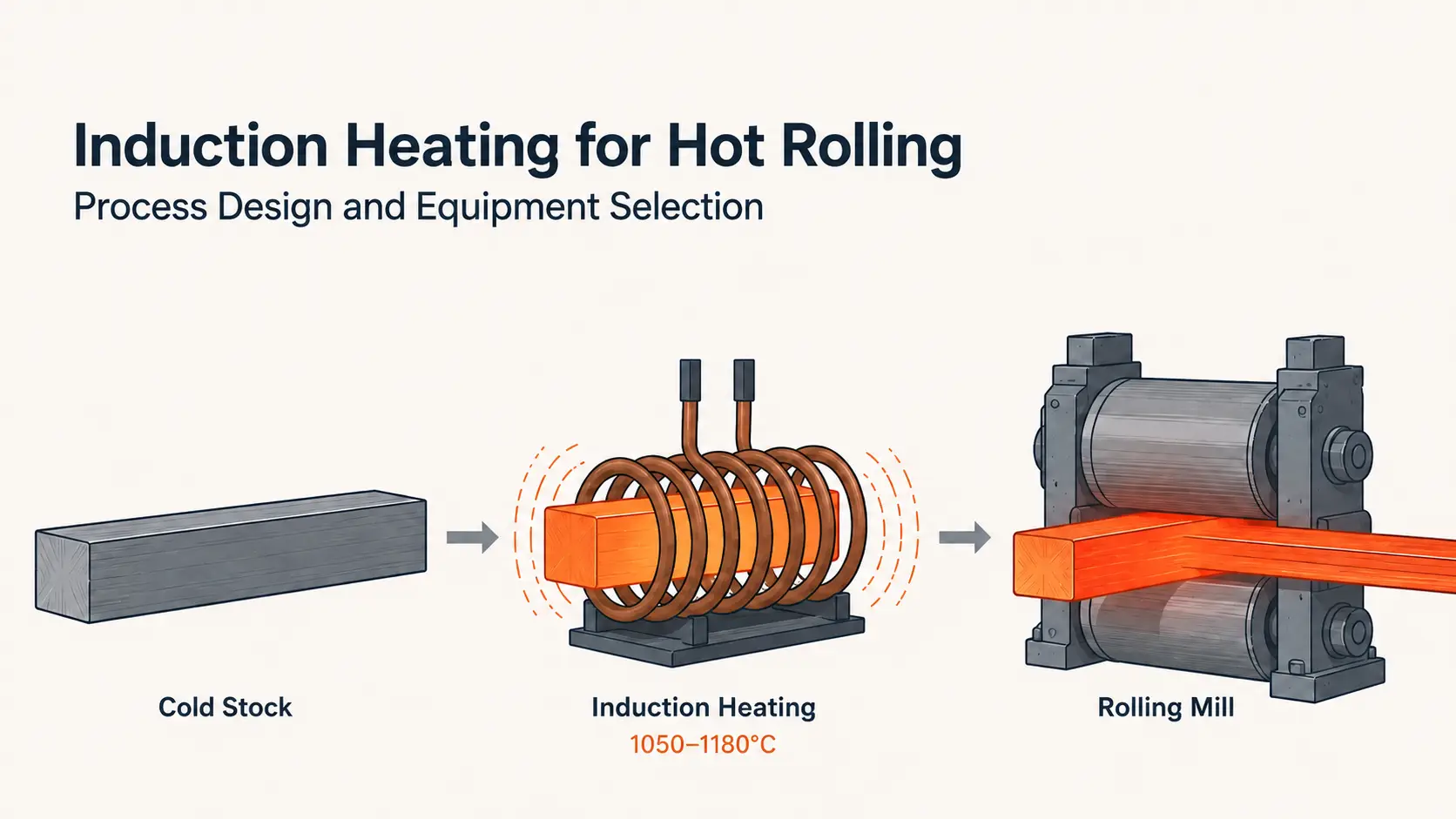
- Induction hot rolling uses electromagnetic induction to heat billets, bars, rods, or strips before they enter a rolling stand. Heat is generated inside the metal — not transferred from a flame or furnace atmosphere. That distinction drives every practical difference in startup time, temperature control, scale formation, and energy consumption.
Induction can serve three distinct roles on a hot rolling line. Which one fits depends on existing equipment, product range, and the temperature control the mill actually needs.
- Primary heating — replace the furnace entirely. Short billets, bar ends, ring blanks, fastener stock, and small profiles are the natural candidates. The system heats only the length that requires rolling. A 300 mm zone on a 3-meter bar does not need the entire stock at 1100°C.
Speed is the other reason this works. A cold induction system reaches full production power in under 60 seconds. A gas-fired furnace needs 10 to 16 hours from cold to charge-ready temperature. Many mills keep furnaces idling at 700°C through weekends just to avoid restarting on Monday. Induction eliminates that idle fuel cost — and the gas bill that comes with it.
- Booster heating — tighten temperature control after the furnace. A mill that already has furnace capacity but cannot hold tight exit temperatures — or loses too much heat during transfer — often benefits most from induction as a temperature trim station. The furnace handles bulk heating. Induction, placed between furnace discharge and the first rolling stand, lifts the stock the final 50°C to 100°C that uneven discharge and transfer time stole. No furnace replacement. No line redesign. Just tighter temperature control at the only point where it affects rolled product — the mill entry.
- Localized heating — heat only the zone that gets worked. Shaft ends for upset forging. Tube ends for reducing. Bar ends for heading. These processes need heat in one defined section while adjacent zones — possibly already heat-treated or finish-machined — must stay cool. Induction concentrates energy in a defined area through coil geometry. A furnace heats the entire part. For these applications, induction is the only practical option.
2. Four Variables That Control Heating Quality
Material grade. Carbon and low-alloy steels heat efficiently below the Curie point — roughly 770°C for iron. Above Curie the steel becomes non-magnetic, and coupling behavior shifts. The same power setting that delivered uniform heating at 700°C can overheat the surface at 900°C.
Hot rolling targets 1050°C to 1180°C for carbon and low-alloy steels — entirely in non-magnetic territory. The heating system must be designed for the regime where it runs, not where it starts. Higher-carbon grades (above 1.0% C) have a lower ceiling, typically around 1050°C. Overheating risk climbs sharply as carbon content rises.
Nonferrous metals — copper, brass, aluminum — heat by different mechanisms. Lower electrical resistivity produces shallower current penetration at a given frequency compared to steel. They often demand higher frequencies or different coil geometries to reach practical heating rates. Application testing before equipment selection is standard practice for these materials.
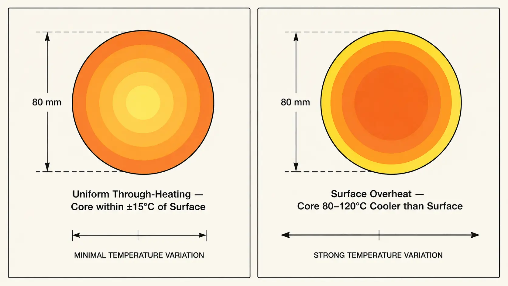
Cross-section and frequency. Frequency controls how deep below the surface induction current penetrates before conduction takes over. For through-heating before rolling, position the reference depth at roughly one-quarter of the bar diameter or billet thickness.
| Bar / Billet Diameter | Recommended Frequency |
|---|---|
| 16–40 mm | 10–50 kHz |
| 40–60 mm | 3–10 kHz |
| 60–80 mm | 2–4 kHz |
| 80–100 mm | 1–2 kHz |
| 100–120 mm | ~1 kHz |
| Over 200 mm | Below 500 Hz |
Get the frequency too high for the cross-section and the surface reaches rolling temperature while the core sits 80°C to 120°C behind. In the mill, the symptom is higher first-pass load, inconsistent spread, and sometimes edge cracking on the colder interior. Undersized power makes it worse — the operator slows the line to compensate, and throughput drops with it.
Line speed and dwell time. Dwell time inside the coil — how many seconds the workpiece absorbs energy — equals coil length divided by line speed. A 2-meter coil at 3 m/s gives about 0.67 seconds of heating per pass. That is not much time to deliver 800°C of temperature rise.
If the mill runs at variable speed — different products, different reductions — dwell time changes constantly. Open-loop power on a variable-speed mill guarantees temperature drift. An induction system needs closed-loop control: a pyrometer at coil exit feeding back to the power supply, holding setpoint as the line accelerates, decelerates, or pauses. The control loop should respond in under 200 milliseconds. Slower than that, and the system chases the temperature rather than holding it.
Temperature measurement. Pyrometers are the standard tool for non-contact temperature reading in hot rolling. They are also the single largest source of systematic error on an induction line.
Scale formation shifts emissivity — a freshly descaled billet reads differently from one that oxidized for 20 seconds in air. Steam from cooling water, smoke from roll lubrication, and ambient reflections from hot surroundings each inject error. A pyrometer aimed through steam or at the wrong angle can read 30°C off true temperature.
The practical fix: two measurement points and trend tracking, not absolute readings. Place one pyrometer at coil exit and one at mill entry. A sensor that reads 12°C low consistently is manageable — the control loop compensates. A sensor whose error drifts as scale builds up on the lens is worse than no measurement at all. The control system corrects for a temperature the workpiece never actually reached.
3. When Induction Wins — and When It Doesn’t
Induction earns its place on a hot rolling line in several specific scenarios. Outside those scenarios, a furnace — alone or paired with induction boost — remains the practical choice.
- Frequent start-stop and size changes. Instant on/off eliminates idle fuel burn between batches and through shift changes. Recipe changes take seconds — adjust power and frequency setpoints — versus the 20 to 30 minutes a furnace zone takes to stabilize at a new temperature. Mills running short campaigns or multiple sizes per shift see the biggest gain here.
- Products where scale directly hits yield. Induction keeps scale loss below 0.5%. Combustion furnaces lose 1.5% to 3% of every billet as iron oxide. On a 500,000-tonne-per-year line, the difference is roughly 5,000 to 12,500 tonnes of saleable steel annually — material that was purchased and heated but never rolled. For high-value alloys, the numbers tilt further toward induction. The same logic applies to processes like hot stamping and connecting rod forging, where surface condition after heating directly affects downstream forming quality.
- Tight temperature windows. Closed-loop induction with pyrometer feedback holds ±15°C at the workpiece. A gas furnace in steady state might hold ±30°C — and significantly worse during speed changes, after a line stop, or when the charge mix varies. For rolling operations where temperature directly affects gauge control, strip profile, or mechanical properties, that difference compounds across every metre of rolled product.
- Partial heating. When only a section of a part needs heat — shaft ends, tube ends, bar ends — induction is the only practical method that does not overheat the rest of the workpiece. This is a binary decision, not a trade-off.
Furnace remains the practical choice when billet sections exceed roughly 300 mm — below 500 Hz, induction power supplies become disproportionately expensive and penetration depth at practical frequencies still relies on conduction for the last portion of the cross-section. A wide product mix with daily size changes across a broad range adds coil changeover cost and complexity; the payoff from induction’s speed and control must be weighed against the tooling investment. And a mill with a fully amortized furnace running near capacity typically gains more from adding induction as a booster than from removing a working furnace.
4. How to Specify a System
What a supplier needs to size an induction power supply, design the coil, and integrate the system into an existing mill:
| Parameter | What the Supplier Needs |
|---|---|
| Material | Grade and full chemistry range |
| Workpiece | Shape, dimensions, and dimensional tolerance |
| Starting temperature | Ambient, preheated from upstream, or from furnace discharge |
| Target temperature | Rolling temperature and required uniformity across the cross-section |
| Production rate | kg/hour or pieces/hour — peak and average, not just nameplate |
| Heating length | Physical envelope where coil and guides fit between existing equipment |
| Transfer | Distance and time from heater exit to first rolling stand |
| Mill constraints | Maximum allowable temperature, speed range, minimum gap between billets |
| Coil changeover | How many sizes, how frequently, how fast the change must execute |
| Electrical supply | Voltage, available kVA, harmonic distortion limits |
| Cooling water | Flow rate, inlet temperature, water quality — closed-loop chiller required? |
| Automation | Standalone panel or full mill PLC integration, billet-level data logging, quality traceability |
For unusual alloys, large sections, tight metallurgical windows, or high-volume lines where a 1% scrap rate represents significant money, invest in sample testing. Heating a small batch of production material under controlled conditions confirms heating time, power level, temperature profile, scale condition, and coil geometry before committing to the full installation. A one-day test catches problems that a six-month commissioning process cannot undo.
Key Takeaway
Induction hot rolling cuts scale loss below 0.5%, starts in under a minute, and holds ±15°C at the mill entry — numbers a furnace alone cannot match on a variable-speed line. The four variables that determine the outcome are material grade, cross-section, frequency, and the feedback loop between pyrometer and power supply. Engineer those four as one thermal system. Size the rest of the installation around them.
Can induction replace a reheating furnace entirely?
Yes — when the part cross-section, throughput, and temperature requirements fall within the induction system’s power and frequency capability. Billets and bars up to roughly 120 mm diameter are the practical ceiling for medium-frequency systems as the sole heat source. Above that, induction typically works best as a booster after furnace preheat rather than as a replacement.
What frequency is right for hot rolling steel billets?
Bars 40–60 mm in diameter typically use 3–10 kHz. Bars 80–100 mm use 1–2 kHz. Sections above 200 mm require frequencies below 500 Hz. The goal is to position the current penetration depth at roughly one-quarter of the diameter so conduction completes through-heating without overheating the surface.
What causes uneven heating in an induction hot rolling line?
Three causes account for most uneven heating problems. Wrong frequency for the cross-section — surface overheats while the core stays cold, showing up as high first-pass load and inconsistent spread. Line speed changes without closed-loop power correction — dwell time drifts and temperature follows. Pyrometer error from scale, steam, or poor sighting — the control system chases a temperature the workpiece never actually reached. Before adjusting process parameters, rule out cooling water problems: low flow, high inlet temperature, or partially clogged coil passages degrade repeatability and are easily missed.
Size Your Induction Hot Rolling System
Send your material, target throughput, and temperature requirements. Our engineering team can evaluate power supply sizing, frequency selection, coil design, and line integration.


