
Induction Heating for Flanges: Process Guide
Flanges carry bolted connections in pipe systems, pressure vessels, wind towers, and heavy machinery. When one needs heat—for assembly, welding, or maintenance—induction delivers it to the flange, not the entire assembly. The process is straightforward on paper. In practice, geometry calls the shots.
1.What Makes Flanges Challenging to Heat
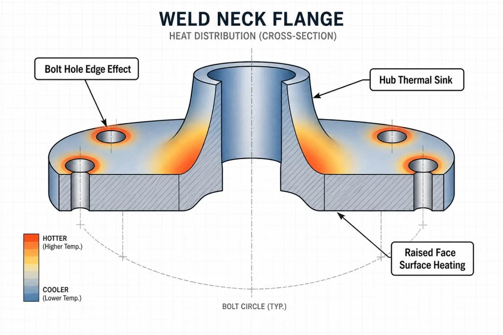
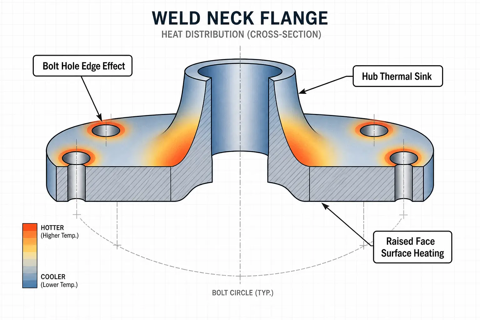
Flanges are circular but rarely uniform. Bolt holes, raised faces, weld necks, hubs, and gasket grooves create thermal mass differences across the part. These features heat and cool at different rates. If the coil geometry doesn’t account for them, temperature spreads unevenly.
Material choice compounds the problem. Carbon steel flanges heat efficiently below the Curie temperature. Stainless steel and nickel alloy flanges don’t. A 24-inch A105 weld neck and a 24-inch 316 stainless blind flange need different power levels, different frequencies—even with the same coil in front of them. For large flanges, the question isn’t whether induction can heat the part. It’s whether the system heats the right zone, at the right rate, without excessive temperature variation or damage to machined surfaces.
2.Where Induction Fits for Flanges
Induction heating for flanges makes sense when the job calls for localized, repeatable heat and the production pace justifies dedicated equipment. A flange gets heated at the assembly station, next to the welding bay, or inline in an automation cell. No furnace transport. No long soak times. The heat turns on when production needs it and stops when the cycle ends—compare that with firing a furnace for a single part or waiting for resistance blankets to ramp. For readers who want the fundamentals behind the process, see how induction heating works.
3.Common Flange Heating Applications
3.1Shrink Fitting and Assembly
The most common flange induction application: thermal expansion for interference fits. Heat the bore or a defined ring section. The flange expands. It slides onto the shaft, pipe, or hub. Cooling locks the fit.
The trick is heating only what needs to expand. Heating the entire flange wastes energy and time. A properly matched coil targets the bore zone. Temperature targets come from the interference calculation—not a guess. Build in enough margin for handling, but don’t overheat. Excessive temperature risks distortion. For more on equipment selection for this type of work, see our guide to induction shrink fitting machine selection.
3.2Weld Preheating
Weld neck flanges and heavy-wall pipe connections often require preheat to control cooling rate and prevent hydrogen cracking. Induction delivers preheat that’s faster to temperature and more uniform than torch methods. With thermocouple or infrared feedback, the system holds the preheat band through the welding cycle. No operator adjusting a flame. No guessing whether the temperature is actually where the code says it should be.
3.3Coating Removal and Maintenance Heating
Pipeline flanges, refinery joints, and heavy equipment often need heat to soften coatings, release sealants, or free corroded bolts during teardown. Induction heats the steel beneath the coating without an open flame. The goal is release, not overheating. Review coating chemistry and ventilation before committing to the process—temperature control matters more here than in assembly heating.
3.4Localized Heat Treatment
Some flanges need hardening on a seal land, stress relieving around a weld zone, or tempering after machining. Induction heats a selected ring or surface without exposing the full part to furnace conditions. These applications demand tighter metallurgical control—cooling rate, soak time, and temperature uniformity all count. See our page on induction hardening when the flange has mechanical property requirements beyond assembly fit.
4.Key Process Variables — and a Material Quick Reference
Three variables drive every flange heating setup: heated zone, temperature uniformity, and cycle time.
Define the heated zone first. Heating the full OD of a 36-inch flange calls for different power and coil geometry than heating only the bore. Getting this wrong cascades into every downstream decision.
Temperature uniformity determines how much engineering goes into coil design, part rotation, and sensor placement. An assembly fit might tolerate ±25°F across the bore. A weld preheat following code won’t.
Cycle time trades off against thermal gradients. Maximum power in minimum time creates steep surface-to-core temperature differences in thick flanges. A slightly longer cycle with a brief soak often produces more uniform results—especially on wall sections above two inches. Part handling matters too. The heating setup should fit the way flanges actually move through the plant, not the other way around.
| Material | Magnetic (Below Curie) | Heating Behavior | Typical Frequency | Watch For |
|---|---|---|---|---|
| Carbon Steel (A105) | Yes | Fast, efficient | 1–10 kHz | Overshoot above Curie point |
| Alloy Steel (F11, F22) | Yes | Fast, efficient | 1–10 kHz | Temper window limits |
| 304 / 316 Stainless | No | Slower, more power needed | 10–50 kHz | Higher thermal expansion than carbon steel |
| Ductile Iron | Yes | Fast | 1–10 kHz | Surface melting at sharp edges |
| Inconel 625 / 718 | No | Slow, high power demand | 10–50 kHz | Low thermal conductivity → steep gradients |
5.Coil Design Considerations
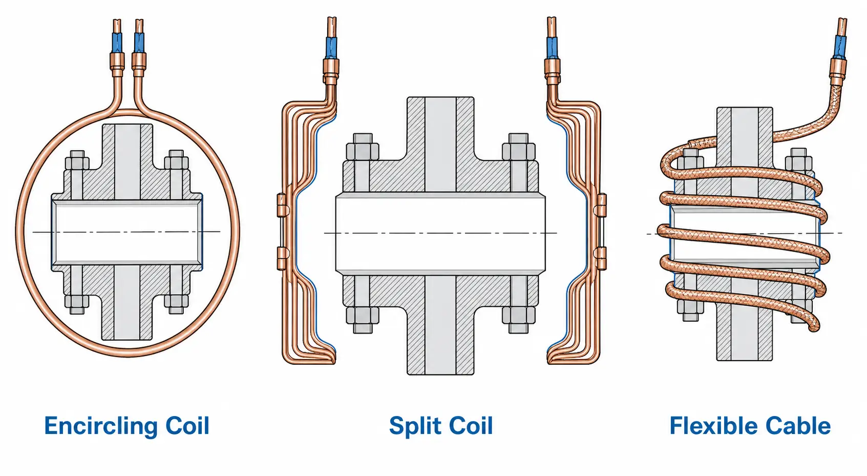
Coil design separates a reliable flange heating process from an inconsistent one. The coil must match the flange diameter, the heated zone, and the way the part moves through production. Smaller flanges work well with circular encircling coils around the OD or bore. Large flanges—wind tower sections, pressure vessel bodies—may need split coils, flexible induction cables, or scanning heads. If the flange stays fixed, the coil must open, clamp, or index around it.
Bolt holes and raised features near the coil can concentrate heat locally. Part rotation or multi-turn coil adjustments help smooth this out. Water cooling is mandatory for production coils carrying high current. The system should include a properly sized induction heating water cooling system with flow monitoring and protection against low-flow conditions. For a broader look at how all the pieces fit together, see our breakdown of induction heating system components. Prototype testing is cheap insurance—one heating trial reveals whether the coil produces acceptable uniformity before the system is finalized.
6.Power, Frequency, and Temperature Control
Power scales with mass, target temperature, and cycle time. A small slip-on flange might need 15–30 kW. A 48-inch pressure vessel flange needs substantially more. Guessing low slows production. Guessing high wastes capital.
Frequency controls where the heat lands in the material. Lower frequencies push deeper—critical for thick-wall flanges where surface-only heating won’t work. Higher frequencies concentrate at the surface. For a deeper explanation, see our guide on how frequency affects induction heating. Match frequency to the required heat depth, not just the fastest surface warm-up.
Temperature control should match process risk. Non-critical expansion work may run on timed heating when parts are consistent. Welding, heat treatment, or tight-tolerance assembly calls for closed-loop control—thermocouple or infrared pyrometer feedback with data logging. Sensor placement matters: an IR sensor aimed at a shiny machined surface reads wrong unless emissivity is managed. Place thermocouples where they represent the critical process temperature, not just where they’re easy to attach. If you’re still sizing the equipment, our guide on how much power you need for induction heating can help frame realistic requirements.
7.Making the Call
Induction fits flange heating when three things line up: the heated zone is well-defined, production volume supports the tooling cost, and temperature control matters enough to justify the equipment. If flanges move through your shop daily—for assembly fits, preheat, or maintenance—induction cuts cycle time and gives you the same heat every cycle.
Heating one flange a month with a loose temperature window? An oven or resistance blanket may serve fine. The dividing line isn’t the flange size—it’s whether repeatability pays for itself. For a side-by-side look at how induction stacks up against traditional heating, see induction heating vs. gas furnace.
Key Takeaway
Flange induction heating works when the coil, power supply, and temperature control are matched to the actual part geometry—not estimated from diameter alone. For a result you can repeat, define the heated zone first, pick the material-appropriate frequency, and don’t trade uniformity for speed.
8.Frequently Asked Questions
Q: What flange materials can induction heat?
A: Most conductive metals—carbon steel, alloy steel, stainless steel, ductile iron, and nickel alloys. Magnetic carbon steels heat fastest. Non-magnetic grades like 316 stainless and Inconel need different frequency and power settings.
Q: Can induction heat large pipe flanges?
A: Yes. But diameter and mass drive the power requirement and coil design. Large flanges often use split coils, flexible induction cables, staged heating, or part rotation to maintain uniformity across the heated zone.
Q: Induction or torch for flange preheat?
A: Induction wins on repeatability, temperature control, and working conditions in a production environment. Torch heating still has a place for occasional field repairs where documentation isn’t required and part shapes vary run to run.
Q: What information do I need to size a flange heating system?
A: Start with the flange drawing, material grade, heated zone, target temperature, and required cycle time. A supplier uses these—plus annual volume, duty cycle, and any applicable code requirements—to recommend power level, frequency range, coil concept, and cooling capacity.
Need an Induction Heating Process for Flanges?
Send us your flange drawing, material grade, target temperature, and cycle time. Our engineering team will review the application and recommend an induction heating configuration for testing or production.


