
Induction Heating for Connecting Rods: Practical Guidance for Heat Treatment, Assembly & Production
Connecting rods carry cyclic loads through a non-uniform shape. The big end, small end, web, cap, and bolt regions each have different mass, different thermal response, and different metallurgical requirements. When a rod needs heat—for shrink fitting a bushing, hardening a bore, or preheating before forming—heating the entire part in a furnace is often the slowest and least precise way to do it.
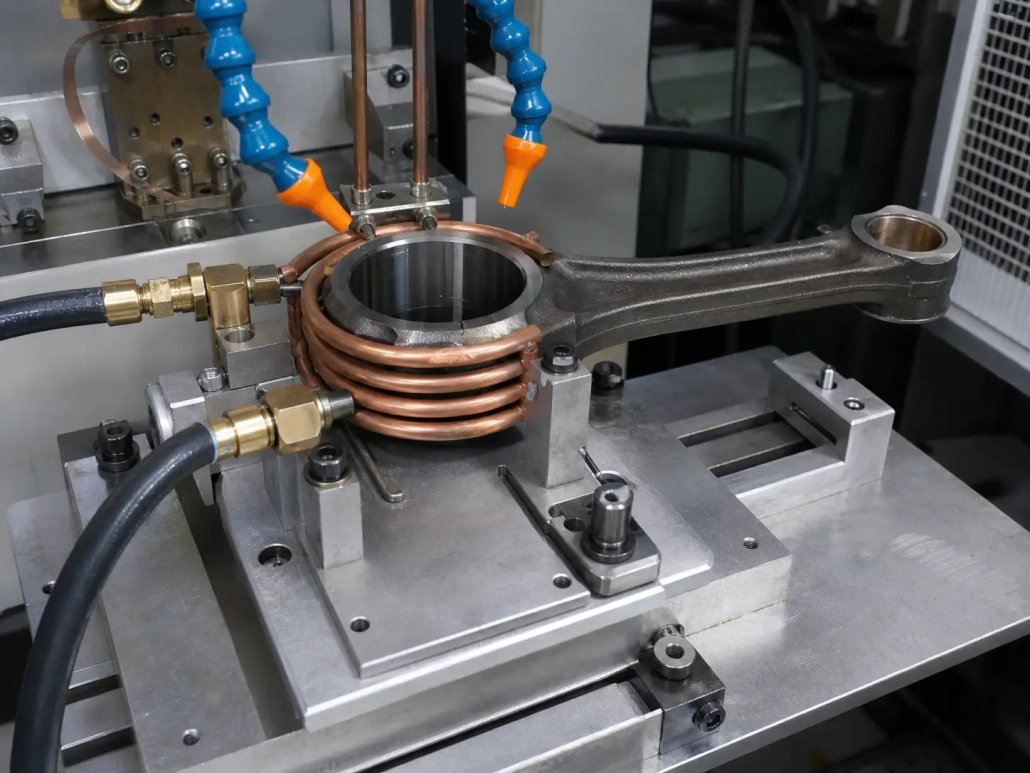
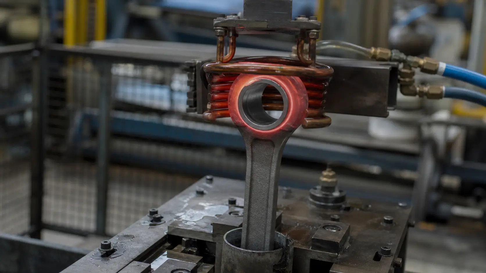
Induction heating connecting rods puts energy directly into the metal at the exact zone that needs it. No waiting for a furnace to ramp. No heating sections that do not require thermal treatment. The electromagnetic field couples with the conductive rod material and generates heat internally—the same principle covered in our induction heating fundamentals guide.
For production, the practical advantages stack up fast: shorter cycle times than batch furnace processing, less oxidation from reduced time-at-temperature, and easier integration into automated cells with presses, robots, and quench stations. The catch is that connecting rod geometry does not forgive sloppy process design. An off-center coil, the wrong frequency, or a fixture that drifts by half a millimeter can turn a repeatable process into a scrap generator.
Why Induction for Connecting Rods
Connecting rods demand localized heat. Shrink fitting needs the bore hot and expanded while the rest of the rod stays cool. Hardening targets a specific wear surface. Forging preheat wants uniform temperature through a section that varies in thickness from 8 mm to 35 mm within the same part.
A furnace treats the entire rod as one thermal mass. That means longer cycle time, more oxidation, and heat soaking into areas that were already in final condition. Induction flips this. The coil surrounds the zone that matters. Energy enters the metal directly at that zone. Everything else stays at ambient or near-ambient temperature.
Three conditions make induction the right call for connecting rod work:
- The heated zone is a bore, an end section, or a bearing seat—not the entire rod. Induction couples precisely where the coil is placed.
- Cycle time matters. A 12-second heat cycle integrated into a press cell beats pulling rods from a furnace tray every 40 minutes.
- Part-to-part repeatability is non-negotiable. A validated time-power recipe with pyrometer feedback produces the same thermal result on rod #1 and rod #10,000.
Common Applications
Induction heating supports four main connecting rod operations. Each has different temperature targets, different coil approaches, and different quality checks.
- Shrink fitting and thermal assembly. The bore is heated to expand by 0.05–0.15 mm, enough to slide in a bushing, sleeve, or bearing race without press force. Uniform circumferential heating is the whole game—a 20°C temperature difference across the bore can cock the insert or leave the bore out-of-round after cooling. An encircling coil around the rod end, a pyrometer aimed at the bore wall, and a fixture that centers the bore in the coil is the standard setup. For more on this application, see our shrink fitting equipment selection guide.
- Localized heat treatment. Connecting rods sometimes need hardening, tempering, or stress relief on specific surfaces—pin bores, bearing seats, contact regions, or locally reinforced sections. Induction heats only those surfaces to austenitizing temperature, followed by a timed quench spray. The rest of the rod stays below transformation temperature. This preserves bulk toughness while putting hardness where the wear happens.
- Forging and forming support. In lines where connecting rods are hot-formed, re-struck, or sized, induction brings the billet or preform to forging temperature in seconds. The fast ramp reduces scale formation compared to extended furnace soaking. Power density and section-thickness matching are critical—a thin web section will overheat long before a thick big-end reaches forging temperature if the frequency and power are not tuned to the mass distribution.
- Brazing and joining. Some rod designs require brazed joints or auxiliary attachments. Induction delivers heat to the joint area without soaking the entire assembly, provided the coil can access the joint and the fit-up is consistent.
Key Process Variables
Four variables control the outcome. They interact—change one and you usually need to revisit the others.
Frequency. Lower frequencies drive current deeper into the part cross-section. Higher frequencies concentrate heat at the surface. Connecting rods span a wide range of section thicknesses within a single part, so frequency selection is a balancing act. The table below gives a starting point for common rod heating tasks.
| Application | Typical Section | Recommended Frequency Range | Heating Objective |
|---|---|---|---|
| Small-end bore shrink fitting | Thin wall, 3–8 mm | 30–100 kHz | Fast surface-to-mid-wall heating, uniform circumferential expansion |
| Big-end bore shrink fitting | Medium wall, 5–15 mm | 10–50 kHz | Deeper penetration for uniform bore expansion through thicker section |
| Bore or bearing seat hardening | Surface layer, 0.5–2 mm case depth | 50–200 kHz | Shallow austenitizing, fast quench transition |
| Forging preheat (whole rod or billet) | Variable, up to 35 mm | 1–10 kHz | Through-heating with minimal surface-to-core gradient |
| Beam or web section stress relief | Moderate, 4–12 mm | 10–30 kHz | Moderate-depth heating below transformation, controlled soak |
Getting frequency wrong shows up fast. Too high and the surface overheats while the mid-wall stays cold. Too low and the cycle drags out, heat spreads into adjacent areas, and throughput drops. For a deeper explanation of how frequency affects heating depth and coupling, see our frequency selection for induction heating guide.
Power level and heating time. These two are a pair. High power + short time gives you fast surface heating with steep thermal gradients. Lower power + longer time lets conduction even out the temperature profile but costs throughput and can spread heat beyond the target zone.
There is no universal power setting. The number comes from part mass, target temperature, cycle time, and coil efficiency—not a catalog rating. Shrink fitting balances fast expansion against surface overheating. Hardening demands rapid ramp with minimum delay before quench. Forging needs enough soak for the core to reach temperature without the surface burning. For sizing guidance, see our power selection for induction heating guide.
Material and prior condition. Connecting rods come in forged steel, powder metal, alloy steel, and cast materials. Electrical resistivity, magnetic behavior, carbon content, and prior heat treatment condition all affect how the part couples with the induction field.
Magnetic steels heat efficiently below the Curie temperature. Above it, coupling behavior shifts and the heating rate changes. This transition happens mid-cycle and affects every rod the same way—if the process is validated. Without closed-loop temperature control or a proven time-power recipe, the Curie transition creates rod-to-rod variation that is hard to trace and harder to fix.
Temperature control. Infrared pyrometers are the most common production solution, but they are only as good as their setup. Emissivity variation from surface scale, oil residue, or viewing angle can shift the reading by tens of degrees. A pyrometer aimed at the bore outer wall while the critical inner surface lags behind gives a false sense of control.
During process development, verify temperature distribution with sacrificial test parts. Thermal paint, embedded thermocouples, or post-cycle metallurgical inspection reveal what the pyrometer misses. The goal is a validated window where the pyrometer reading correlates reliably with the actual temperature at the point that matters.
Coil Design and Part Handling
Connecting rods are not simple cylinders. The offset geometry, changing mass distribution, and nearby features—bolt holes, cap split lines, thin web sections—all pull heat away from the target zone or create localized hot spots. Coil design has to account for every one of these features.
Coil shape and coupling. Bore heating typically uses an encircling coil around the rod end. The coil surrounds the bore area and heats it uniformly around the circumference. Internal coils work where access allows and the bore diameter is large enough. Shaped coils target one region while avoiding another—useful when a bolt boss sits 6 mm from the heated zone and must not reach 200°C.
Coupling distance matters more than most first-time users expect. A 0.5 mm shift in coil-to-part gap changes the electromagnetic coupling and shifts the heating pattern. End effects at coil edges can create hot bands or cold bands. Corners and thin sections concentrate current and overheat faster than adjacent thicker sections. Every one of these behaviors is predictable—and manageable with proper coil geometry. For design principles, see our induction coil design guide.
Fixturing and repeatable positioning. Small position changes create measurable temperature differences. This is especially unforgiving when the coil-to-part gap is tight or when heating only one end of the rod. The fixture must locate the rod using repeatable datums—bore center, side face, cap orientation, insertion depth.
If the line runs multiple rod sizes, plan for quick-change tooling or adjustable coil positions from the start. Retrofitting flexibility later costs more.
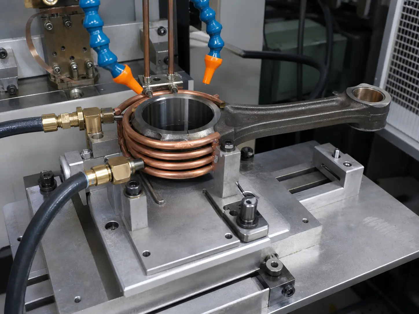
Cooling water. Induction coils, power supplies, bus bars, and transformers all need controlled cooling. Compact coils running high duty cycles on a connecting rod line put serious thermal load on the cooling circuit. Undersized cooling leads to coil overheating, insulation breakdown, and unplanned downtime.
A properly designed water cooling system for induction heating controls flow rate, pressure, conductivity, temperature, and filtration. If quench hardware shares the cooling loop, factor in the additional heat load from the quenchant return.
Quality Risks and How to Reduce Them
A validated induction process is repeatable. An unvalidated one is reliably bad. Four risks show up most often in connecting rod work.
Bore distortion. Uneven circumferential heating expands the bore non-uniformly. It goes out of round during heating and stays out of round after cooling. Center the bore in the coil. Use a coil geometry that delivers balanced heating around the full circumference. Control the heating rate—overshooting the target temperature by 30°C because the pyrometer was aimed wrong turns a good part into scrap. Validate with post-heating bore measurement on first-article samples, not just on the production pyrometer display.
For shrink fitting, the target is not just reaching temperature. The bore needs enough expansion for clean assembly while returning to within-roundness spec after cooling. These two requirements sometimes pull in opposite directions and need to be balanced during process development.
Hardness variation. Soft spots, excessive hardness, shallow case depth, or cracks—all trace back to uneven heating, inconsistent quenching, or material variation. The quench system deserves as much engineering attention as the coil. Spray pattern, flow rate, pressure, quenchant concentration and temperature, and the delay between heat-off and quench-on all affect the final microstructure.
When the process resembles localized hardening of a bore or bearing surface, reviewing common induction hardening defects during development saves time later.
Overheating and grain growth. Connecting rods live under cyclic loading. Excessive temperature or extended time at temperature degrades mechanical properties, grows grain structure beyond specification, and increases scale. Overheating often starts innocently—an operator bumps up power or adds a second of heating time to compensate for a dull coil, a dirty part, or a fixture that shifted. A locked recipe with a validated process window prevents these adjustments from becoming the new normal.
Surface contamination. Oil, machining coolant, rust preventative, or surface scale change how the part couples with the coil and how the pyrometer reads the surface. Contamination also produces smoke, deposits on the coil, and inconsistent emissivity. Parts should enter the induction station clean and dry. Upstream process control at wash or machining is as important as the induction equipment itself.
Equipment Selection
Equipment selection starts with the part, not the catalog. The supplier needs the rod drawing, material specification, heated zone dimensions, target temperature, cycle time, and production environment before recommending a configuration.
Power supply. Match the frequency and power range to the application. Verify the duty cycle rating against the production rate. Look beyond peak kilowatts: load matching capability, closed-loop control options, recipe storage for multiple rod sizes, PLC integration, and diagnostic reporting all determine whether the system runs steadily or becomes a maintenance headache.
Recipe management matters when the line runs more than one rod design. Operators select the correct program for each part number. Critical parameters stay locked. The alternative—manual adjustment per batch—produces exactly the kind of variation that induction is supposed to eliminate.
Automation and integration. Connecting rod heating rarely stands alone. The induction system communicates with presses, robots, conveyors, and quench stations. Part presence sensing, temperature verification, and cycle data logging prevent bad parts from reaching assembly. Map the full sequence—loading, positioning, heating, transfer, assembly or quench, unloading—before committing to equipment specs. A 6-second heat cycle feeding a 12-second press is fine. A 14-second heat cycle ahead of an 8-second press is a bottleneck.
Application testing. For new or technically sensitive processes, test before buying. Use actual production material, not lab samples. Include worst-case dimensions—the rod at maximum bore with minimum wall thickness. Map temperature, measure hardness, check bore before and after heating, verify cycle time under realistic loading. A day of testing costs less than a week of troubleshooting a system specified from a datasheet.
When Induction Makes Sense
Induction is the right tool when the connecting rod needs fast, localized, repeatable heat and the alternative—furnace, torch, or resistance—costs you in cycle time, distortion, oxidation, or process control.
— Only the bore, end section, or bearing seat needs heat. Heating the whole rod wastes energy and risks dimensional change in finished areas.
— Cycle time is measured in seconds, not minutes. A furnace tray takes 30–40 minutes. An induction coil takes 6–15 seconds.
— Dimensional control is tight. Induction heats one zone. Post-cooling distortion is smaller and more predictable than with whole-part furnace heating.
— Part-to-part repeatability is non-negotiable. A validated recipe with temperature feedback delivers the same result across shifts, operators, and seasons.
Induction is not the answer when volume is very low, coil access is impractical, or the application needs long uniform soaking of the entire component. For those cases, furnace or resistance heating fits better. For the majority of connecting rod work—shrink fitting a bushing, hardening a bore, preheating before forming—induction delivers speed and control that other methods cannot match. For a broader look at how induction fits into automotive manufacturing, see our induction heating for automotive parts guide.
Key Takeaway
Induction heating connecting rods puts controllable, repeatable heat exactly where the process demands it—shrink fitting, hardening, forging, or assembly. Success turns on getting four things right: frequency matched to section thickness, a coil shaped for the specific rod geometry, a fixture that locates the part the same way every cycle, and a validated temperature window that catches drift before it catches parts.
Frequently Asked Questions
Q: What parts of a connecting rod can be induction heated?
A: The small-end bore, big-end bore, bearing seats, pin bore areas, cap region, and selected wear surfaces. Which zone you heat depends on the operation—shrink fitting targets bores, hardening targets bearing surfaces, and forging preheat may cover the entire rod or a specific section.
Q: Is induction heating suitable for connecting rod shrink fitting?
A: Yes. It is one of the most common connecting rod induction applications. The key requirement is uniform circumferential bore heating so the bushing or bearing race slides in without excessive force and the bore returns to round after cooling. An encircling coil, centered fixturing, and pyrometer verification at the bore wall are the standard setup.
Q: How do you choose the right induction frequency for connecting rods?
A: Match frequency to the heated zone section thickness and the required heating depth. Small-end bores with thin walls typically use 30–100 kHz. Big-end bores with thicker sections run at 10–50 kHz. Surface hardening of bearing seats may need 50–200 kHz. Forging preheat through variable cross-sections uses lower frequencies, typically 1–10 kHz. Application testing with production-material samples is the most reliable way to confirm.
Q: What are the main risks when induction heating connecting rods?
A: Bore distortion from uneven heating, hardness variation from inconsistent quench or temperature control, overheating that degrades microstructure, and surface contamination that throws off both coupling and pyrometer readings. All four risks are manageable with proper coil design, validated recipes, clean incoming parts, and regular process checks.
Need an Induction Heating Process for Connecting Rods?
Send us your part drawing, material spec, target temperature, and cycle time. Our engineering team will review the application and recommend an induction heating configuration for testing or production.


