
Induction Heating for Metal Drawing: Improving Formability and Production Efficiency
Table of Contents
Cold-draw stainless steel wire through six consecutive dies and by the fourth pass the material pushes back. Drawing force climbs. Surface micro-tearing begins. The die wears into a new profile. You anneal between passes to reset ductility—and that means pulling coils offline, firing a furnace, and waiting. Induction heating for metal drawing keeps the line running. It brings heat to the material in seconds, directly between the payoff and the die, without breaking the production flow.
Metal drawing reduces cross-section by pulling wire, tube, or bar through a progressively tighter die series. The process is simple in concept and merciless in practice: every pass work-hardens the material. Enough passes without intermediate heat and one of three things gives—the wire snaps, the surface tears, or the die wears out of tolerance. Induction preheating lowers flow stress before the material hits the die, so drawing force drops and the reduction per pass can increase.
1. Why Induction Heating Matters Before Drawing
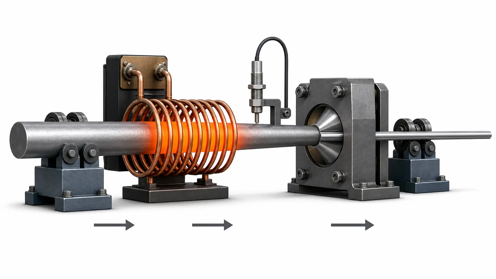
Drawing is a cold-forming process—until the material work-hardens past the point where the draw bench can pull it. Every point of plastic strain raises the flow stress required for the next pass. At some stage the wire snaps, or the surface tears, or the die wears beyond tolerance. The fix is heat before the deformation zone, and induction delivers it online.
Three things change when induction sits between payoff and die:
- Lower flow stress. Heat the material before the die and the force needed to pull it through drops. The effect is localized—hot at the deformation zone, cooling rapidly after exit. More reduction per pass, fewer passes overall.
- Fewer surface defects. Stainless steels, titanium alloys, and nickel-based grades have narrow ductility windows at room temperature. Preheating widens that window. Surface tearing and edge cracking drop when the material flows instead of fractures.
- In-line continuous operation. No batch furnace to load and unload. The coil sits on the line between payoff and first die. Material passes through at line speed. Temperature stabilizes in seconds at startup. Stop the line, heating stops. Restart, and the material is at target temperature before the first meter reaches the die. The equipment pays for itself in throughput, not in energy savings alone.
2. Induction vs Furnace Heating Before Drawing
The practical difference between induction and furnace preheating for drawing is not just speed. It is whether heat integrates into the line or dictates the line layout. A furnace is a separate station—material arrives, waits, heats, and leaves. Induction bolts onto the existing drawing line.
| Factor | Furnace Heating | Induction Heating |
|---|---|---|
| Heating speed | Minutes to hours, depends on batch mass | Seconds, regardless of batch size |
| Line integration | Offline—requires batch handling between furnace and drawing bench | Online—coil mounts directly before the die |
| Temperature control | Broad zone control, thermal lag on adjustment | Closed-loop pyrometer feedback, sub-second response |
| Oxidation | Extended soak at temperature increases scale formation | Short dwell limits oxide growth; atmosphere control is optional, not mandatory |
| Energy efficiency | Heats furnace lining, atmosphere, and surroundings along with the workpiece | Energy deposited directly into the material; no standing losses at idle |
| Startup and shutdown | Long ramp-up and cool-down cycles | Instant on/off; no thermal mass to bring to temperature |
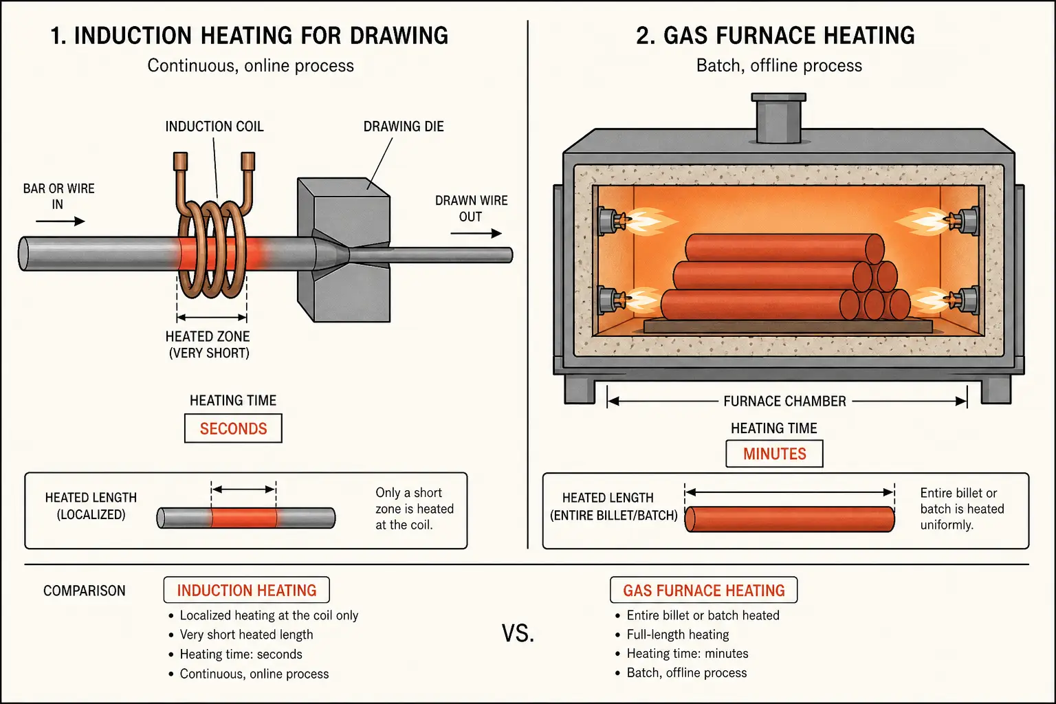
Furnaces still make sense when the entire coil needs uniform temperature before the first die, or when the material cross-section is too large for practical induction penetration, or when an intermittent line uses the furnace as a thermal buffer. The decision turns on whether your process needs heat storage or heat on demand. Continuous lines benefit from on-demand. Batch shops may find a furnace simpler. See induction heating vs gas furnace for the broader comparison.
3. Material-by-Material Heating Considerations
Different alloys respond differently. What works for 304 stainless will not work for C110 copper—the physics changes and the process window shifts with it.
- Stainless steel (304, 316, duplex). Moderate resistivity makes these efficient induction targets. The temperature window is the main concern: too cold and drawing force barely drops; too hot and oxidation or property shifts appear. Preheating to 150–400°C typically delivers the ductility gain without metallurgical side effects. Closed-loop control matters—stainless does not give you a wide margin between “hot enough” and “too hot.”
- Titanium alloys. Low thermal conductivity is the defining challenge. Heat concentrates at the surface, creating a hot skin over a cold core that deforms unevenly at the die. Lower power density and longer coil dwell help the temperature even out. Atmosphere protection may be necessary to prevent alpha-case. For more on titanium’s induction behavior, see induction heating for titanium alloys.
- Copper and copper alloys. High conductivity makes these the hardest to heat—currents flow easily and generate less resistive heat. Lower frequency and multi-turn coils help compensate. Brass and bronze, with lower conductivity, heat more readily. Pure copper drawing often relies on induction for inter-pass annealing rather than pre-die preheating.
- High-strength steel (carbon, alloy, boron). Ferromagnetic at lower temperatures, these grades absorb energy efficiently until they pass the Curie point. Preheat from 200 to 600°C covers most scenarios, and the material forgives minor temperature variation better than stainless or titanium. The main payoff: larger reduction per pass with less die wear. Nickel-based superalloys follow the same low-thermal-conductivity cautions as titanium. See induction heating for superalloys.
4. Frequency, Power, and Coil Design
Three parameters determine whether induction preheating works on a drawing line. Get one wrong and the die receives material that is too cold, too hot, or unevenly heated.
- Frequency. Higher frequencies heat a thin surface layer; lower frequencies drive current deeper. For wire under 5 mm diameter, higher frequency keeps heat localized. For bar and tube above 15 mm, lower frequency ensures the core reaches temperature before the die. The starting point is the material’s reference depth at the target temperature—frequency follows from that calculation, not from a catalog.
- Power. Power must match the thermal demand of moving material. The calculation starts with mass per unit time, specific heat, and target temperature rise. Line speed is the multiplier: double the speed, double the power. Undersized power means the material never reaches temperature. Oversized power wastes energy and risks overheating the surface before the core catches up.
- Coil design. For round wire and rod, a cylindrical multi-turn coil is the default—simple and easy to align with the drawing axis. For tube, the coil bore must accommodate the diameter without losing coupling efficiency. For flat or profiled stock, coil geometry follows the cross-section to maintain consistent gap. Coil length is a trade-off: longer coils heat more evenly but cost more and demand more power. Shorter coils are cheaper but need tighter process control.
5. Where Induction Drawing Delivers Results
| Industry | Typical Materials | What Induction Solves |
|---|---|---|
| Wire manufacturing | Stainless wire, spring wire, welding wire | Fewer intermediate anneals, higher line speed, less wire breakage at the die |
| Tube drawing | Stainless tube, copper tube, aerospace-grade thin-wall tube | Uniform wall reduction, reduced wrinkling, fewer draw-bench stoppages |
| Automotive components | High-strength wire, precision shafts, formed profiles | Consistent mechanical properties pass-to-pass, reduced die wear on high-volume lines |
| Aerospace manufacturing | Titanium alloy components, nickel alloy parts | Process window control for difficult grades, surface integrity preservation |
6. Selecting an Induction System for Your Drawing Line
Not every induction power supply and coil combination works for every drawing application. Five factors determine whether the system fits the line—or becomes an expensive bottleneck.
- Material type and diameter range. The material’s electrical and thermal properties determine frequency, power density, and coil geometry. A system sized for 304 stainless wire will struggle with copper. Define the material envelope first, then size for the hardest-to-heat material in that envelope.
- Line speed and throughput. Power demand scales directly with how fast material moves through the coil. Size for maximum line speed, not average—the system must deliver at peak throughput without overheating.
- Target temperature and tolerance. The narrower the acceptable band, the more control infrastructure you need. Closed-loop pyrometer feedback is standard for tight process windows. For forgiving materials, open-loop with periodic verification may be enough.
- Coil integration. The coil must fit between payoff and first die. On existing lines, measure the gap before specifying coil length. Mounting must handle vibration and thermal expansion. Quick-change connections reduce downtime during size changeovers.
- Cooling and utilities. Power supplies and coils need water cooling. Closed-loop chillers keep water quality consistent. Plan cooling capacity to match power supply rating plus headroom for warm ambient conditions. Undersized cooling means thermal throttling—and the material arrives at the die below target temperature.
Key Takeaway
Induction heating for metal drawing lowers flow stress at the deformation zone, keeps the line running, and pays for itself in throughput. Match frequency, power, and coil geometry to your material and line speed. Get those three right and the rest follows.
Q: Can induction heating be retrofitted to an existing drawing line?
A: Yes, provided there is space between the payoff and the first die for the coil assembly. Most multi-turn cylindrical coils need 300–800 mm of clear path. The power supply can sit separately. Tight layouts may need a custom short coil, trading some heating uniformity for fit.
Q: Does induction preheating affect the surface finish of drawn material?
A: It can—in both directions. Properly controlled preheating reduces surface tearing by improving material flow through the die. Overheating or uneven heating creates oxidation or hot spots that transfer to the drawn surface. The key is temperature uniformity along the length and around the circumference at the die entry. A well-fitted coil with consistent coupling gap delivers this.
Q: What materials are poor candidates for induction preheating before drawing?
A: High-conductivity pure copper is the hardest to heat efficiently and often relies on conventional annealing instead. Materials with cross-sections below 1 mm absorb limited energy per pass. Materials requiring narrow temperature windows with long soak times may also be better served by furnace-based methods.
Need Induction Heating for Your Drawing Line?
Tell us your material, diameter range, and line speed. We will recommend a power supply and coil configuration that fits your process.


