
Steel Billet Induction Heating for Square Billet Forging
Steel billet induction heating is the pacing constraint in more forging lines than anyone admits. The press, the robot, the operator — all three can move faster than the billet heater can deliver uniform forging temperature. And when the heater falls behind, everything behind it stacks up.
Picking a power supply by tonnage won’t size your induction heater. Billet size, steel grade, target temperature, cycle time, frequency, coil length, material handling, scale control, and temperature uniformity all matter. Miss one and the line won’t hit production rate under plant conditions — not on paper, not on the shop floor.
Here are the seven decisions that separate a heater that keeps up from one that becomes the bottleneck.
1. Why Billet Heater Sizing Starts With Cycle Time
A forging line heater is sized around required parts per hour, not billet diameter alone. First question: how many billets must reach forging temperature every minute without holding up the press?
If a press needs one billet every 12 seconds, the induction system delivers a fully heated billet at that interval — including time for indexing, transfer, temperature verification, rejected billets, and short production interruptions. A line designed exactly at calculated capacity falls behind the moment billets vary in size, incoming material temperature shifts, or an operator slows the transfer sequence.
The required heater output needs margin above the theoretical rate. How much depends on the operation, but 10–15% above calculated throughput is a practical floor. Less than that and every minor upset puts the press in wait mode.
The sizing inputs that feed the calculation:
— Billet material and grade
— Billet diameter or cross-section across flats
— Billet length and weight
— Incoming temperature and target forging temperature
— Required billets per minute or parts per hour
— Acceptable temperature gradient, line layout, and handling method
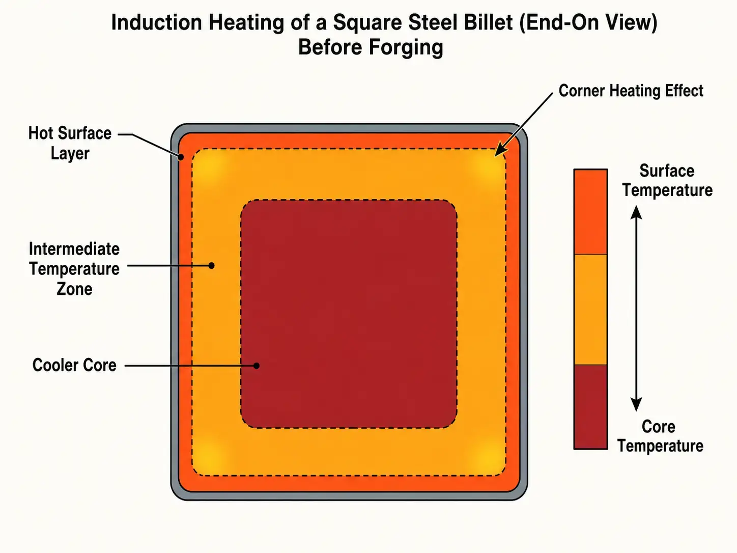
Square billets complicate every one of those inputs. A square does not heat like a round of equal area. Corners and flat faces couple differently, and the coil, frequency, and indexing strategy all shift because of it. That theme runs through every section below.
For a broader look at how induction forging fits into the production line, including equipment selection and process integration, see the full forging guide.
2. Steel Billet Induction Heating Power Requirements
The basic power requirement comes from the energy needed to raise the billet from its starting temperature to forging temperature within the available time. For carbon and alloy steels, forging temperatures land between 2,000°F and 2,300°F, depending on grade and process.
Start with billet weight, temperature rise, specific heat, and production rate. More mass and faster cycle times demand more kW — that relationship is linear with throughput. Then add power for system losses, scale, radiation, coil efficiency, and practical operating margin. The math is straightforward; the assumptions are where most sizing efforts go wrong.
Installed kW must account for electrical and thermal efficiency. Induction heating is efficient next to fuel-fired methods, but not all input power turns into useful heat in the billet. Coil losses, power supply losses, water-cooled copper losses, and radiation from hot steel all cut into net heating efficiency. A well-designed line runs 60–65% overall efficiency. Size below that and you bake in underperformance from day one.
As a quick reference: a line heating 4 lb billets every 10 seconds needs dramatically less power than one heating 25 lb billets at the same interval. Same cycle time, very different energy per part. That is why billet weight and throughput rate drive the calculation, not diameter alone.
Duty cycle matters too. Forging lines run continuously for long shifts. The power supply rating must support production power without thermal derating at the end of an eight-hour run. Power selection and utility planning need attention early in the project — not after the equipment is ordered.
Accounting for Heat Losses
Heat loss climbs fast as billet temperature rises. Near forging temperature, radiation becomes a real factor — especially with any gap between coil exit and press. A heater that hits the right exit temperature during commissioning falls short in production if hot billets queue or lose heat before the press. Size for the actual sequence from coil exit to die contact, not just the heater.
3. Frequency Selection for Round and Square Billets
Frequency controls how deep current penetrates the billet and where heat develops. Lower frequencies push heat deeper into the section. Higher frequencies keep it near the surface. The difference stops being academic when you are trying to heat a 4-inch billet all the way through.
For billet forging, the goal is through-heating — bringing the entire cross-section to forging temperature. Frequency balances heating rate, section size, temperature uniformity, and what the power supply can deliver.
| Billet Size (Across Flats) | Recommended Frequency | Why |
|---|---|---|
| Under 2″ | 3–10 kHz | Small section — surface-to-core distance short enough for medium frequency to heat through |
| 2″–4″ | 1–3 kHz | Deeper penetration needed; balances heating rate with core temperature |
| Above 4″ | 500 Hz–1 kHz | Large section demands deep penetration; higher frequencies overheat the surface before the core catches up |
The final choice also depends on steel grade, target temperature, and how tight a gradient the process tolerates.
Square billets complicate frequency selection. Corners and flat faces do not couple the same way, so they do not heat the same way. Depending on billet size and coil design, corners run hotter than the core — or colder than the mid-face — and both are problems at the press.
For square billets, the frequency decision turns on cross-section across flats, corner temperature behavior, core temperature at discharge, whether billets are indexed or pushed continuously, coil style and coupling distance, and the temperature variation the process can tolerate.
For a deeper technical review, see frequency selection and induction heating fundamentals.
4. Coil Length, Throughput & Material Handling
Installed kW determines how much energy is available. Coil length and billet residence time determine whether the billet can absorb that energy without the surface running away from the core. A short coil with very high power overheats the surface before the center reaches forging temperature — the pyrometer says go, the press says no.
Residence time is the time each billet spends inside the active heating zone, controlled by coil length, billet travel speed, spacing, and indexing method.
For a continuous pusher-style heater, billet pitch directly affects throughput. Tight spacing packs more billets into the coil and improves production rate, but it also changes coupling, temperature control, and mechanical feeding reliability. For an indexing system, each billet stops at one or more heating stations. That simplifies part tracking and temperature control, but the index time must align with the press cycle — no gaps, no overlaps.
Single-Coil vs Multi-Coil Arrangements
A simple heater uses one long coil with a single power supply. Multi-zone systems handle rapid initial heating, final temperature trimming, multiple billet sizes, and closed-loop pyrometer feedback without retooling — essential when incoming material temperature or billet dimensions vary across a production run. For equipment configurations, see induction forging systems and coil design for the details that affect production performance.
Material Handling Affects Throughput
Material handling decides whether the calculated coil throughput is achievable. A heater can have enough kW, and poor feeding, indexing, or discharge design still limits the line. Square billets jam. They always jam at the worst time — skewing or bridging if the rails, pushers, stops, and transfer nests are not designed for hot-scale conditions. The handling design has to account for what happens after weeks of scale buildup, not day one.
— Billet loading method and cold billet magazine design
— Pusher force and alignment under thermal expansion
— Guide rail material, wear, and scale clearance
— Robot, conveyor, or manual pickup timing
The discharge system matters most. A billet leaves the coil at the correct temperature and loses heat every second before the press hits it. Put the coil exit as close to the press or transfer robot as floor space allows, with enough clearance for safe access and maintenance. Every foot of transfer distance costs you temperature — and the hotter the billet, the faster it loses heat.
Hot billet tracking becomes important when multiple billet sizes or recipes run through the same line. The control system needs to know which billet is in which coil position, what recipe is active, and whether any billet has been delayed beyond the acceptable time window. Miss that and you ship a cold billet to the press.
5. Temperature Uniformity and Soak Requirements
A billet can show the correct surface temperature and still be too cold in the core. This is the single most common reason a forging line struggles after installation. The pyrometer reading looks fine. The press disagrees.
The press responds to the billet’s deformation behavior, and that depends on the full temperature distribution through the section — not just the surface. A cold core increases forming load, reduces die life, causes laps or folds, and produces inconsistent grain flow. None of those show up on the heater’s temperature display.
Temperature uniformity depends on billet cross-section, heating frequency, heating rate, coil length, steel thermal conductivity, time available for conduction, where the pyrometer is aimed, and the delay between heating and forging.
For larger billets, a short equalizing or soak section helps. In induction, this does not always mean a separate furnace. It can be a longer coil with reduced power density in the final zone, controlled billet spacing, or a short insulated transfer section that lets heat conduct from surface to core before the press hits.
Build temperature measurement into the line. A single pyrometer aimed at one surface misses corner-to-core differences and orientation-related variation on square billets.
For processes involving downstream heat treatment or hardening, the same temperature control principles apply. Related topics include heat treatment and induction hardening.
6. Cooling, Controls, and Practical Line Integration
A billet heater is a production machine. Beyond the power supply and coil, it depends on cooling, controls, sensors, guarding, maintenance access, and integration with the forging cell. Any one of those can stop the line.
Water cooling is critical. Induction coils, bus bars, leads, and power electronics generate heat during operation. Insufficient cooling reduces reliability, shortens component life, and causes nuisance shutdowns during long production runs. A system that works at 70°F ambient trips on overtemperature at 95°F in August.
| Component | What Needs Cooling | Failure Mode If Undersized |
|---|---|---|
| Induction coil | Copper turns + refractory liner | Coil burnout, refractory cracking |
| Power supply | IGBTs / SCRs + heat sinks | Thermal derating, shutdown mid-shift |
| Output transformer | Windings + core | Insulation breakdown, arcing |
| Bus work | Copper bus bars + bolted connections | Hot spots, loose joints from thermal cycling |
| Capacitors | Dielectric + internal bus | Capacitance drift, reduced life, thermal runaway |
Cooling system design must account for water quality, flow rate, temperature rise, filtration, conductivity, and leak detection. For the full breakdown, see water cooling systems.
Controls support normal production and abnormal conditions. At minimum, most forging heaters need recipe management, power control, temperature monitoring, interlocks, fault logging, and communication with upstream and downstream equipment.
— Billet presence detection and jam detection
— Automatic power adjustment with pyrometer feedback
— Recipe storage by billet size and steel grade
— Reject chute control for under-temperature billets
— Press-ready and heater-ready signal exchange
Automation engineers define signal exchange early. The heater, robot, press, conveyors, and safety system all need to agree on when a billet can move, when heating pauses, and what happens after an upset. Retrofit those handshakes later and the cost multiplies.
7. Common Sizing Mistakes That Reduce Output
Most billet heating problems start with incomplete sizing assumptions. The system checks out on paper. In production, it will not hold rate.
| Sizing Mistake | What Happens on the Shop Floor |
|---|---|
| Sizing by billet diameter alone | Cycle time does not match the press — line runs below rated output |
| Surface temperature only, no core verification | Press overload, die damage, cold folds in the forging |
| Coil too short for the kW applied | Surface scorches before the center reaches forging temperature |
| Coil exit too far from the press | 50–100°F lost in transfer between heater and die |
| Cooling system sized for winter ambient | Overtemperature trips every August afternoon |
| One recipe for three billet sizes and two grades | Some billets underheated, some overheated — no setting works for all |
| No scale clearance in guide rails | Jams, skewed billets, unexpected downtime |
Throwing more kW at the problem can make it worse. Higher power shortens heating time, but it spikes the surface temperature if the coil, frequency, and residence time are not matched to the billet. Coil design matters just as much: geometry, copper section, insulation, refractory, cooling passages, and mechanical support all affect what happens in production.
If the heated billet feeds an induction hardening or heat treatment operation later in the plant, temperature variation creates downstream quality issues. For hardened parts, reviewing common induction hardening defects helps trace how heating variation affects final properties.
Key Takeaway
Size for cycle time, not kW. Get the coil long enough so the core catches up. Put the coil as close to the press as floor space allows. Plan for more than one billet size from day one. Get those four things right and the rest follows.
FAQ
Q: How do I figure out the kW I need?
A: Start with billet weight, target temperature minus incoming temperature, and parts per hour. That gives you the net energy. Apply system efficiency — 60–65% is a reasonable starting point for a well-designed induction line — and add 10–15% margin. Check whether the utility feed can deliver that at full duty before you order.
Q: My billets are square. What frequency should I use?
A: Under 2 inches across flats: 3–10 kHz. 3–6 inches: 1–3 kHz. Above 6 inches: 500 Hz to 1 kHz. Coil design and corner handling shift the final number — test with instrumented billets if the process is new.
Q: My pyrometer says 2,200°F but the press is struggling. What is going on?
A: Cold core. The surface hit forging temperature but the center did not. Slow down the heating rate, lengthen the coil, or add a soak zone at reduced power to let heat conduct inward. A pyrometer only sees the surface.
Q: One coil or multiple heating zones?
A: Single coil works for one billet size at a steady rate. Go multi-zone if you are running multiple billet sizes or steel grades, need tight exit temperature control, or want closed-loop pyrometer feedback. Multi-zone costs more upfront but pays off when your mix changes week to week.
Get a Sizing Estimate for Your Billet Heating Line
Send us your billet dimensions, steel grade, target temperature, and required cycle time. We will put together a power estimate, frequency recommendation, and coil configuration for your layout — typically within 24 hours.


