
Induction Stress Relieving: Is It Right for Your Parts — and Which System Fits?
Induction stress relieving puts controlled heat exactly where residual stress lives — the weld zone, the machined section, the pipe joint — without moving the part into a furnace. For pressure piping, heavy shafts, and fabricated structures, that changes the economics of the whole job.
Residual stress is patient. It waits through finish machining, through hydrotest, through the first months of service — and then it moves the part or cracks the weld. Stress relieving exists to spend that stress on your schedule instead.
This guide covers what the process does, when it beats a furnace, and how to spec a system that holds temperature and proves it on paper.
1. What Induction Stress Relieving Does
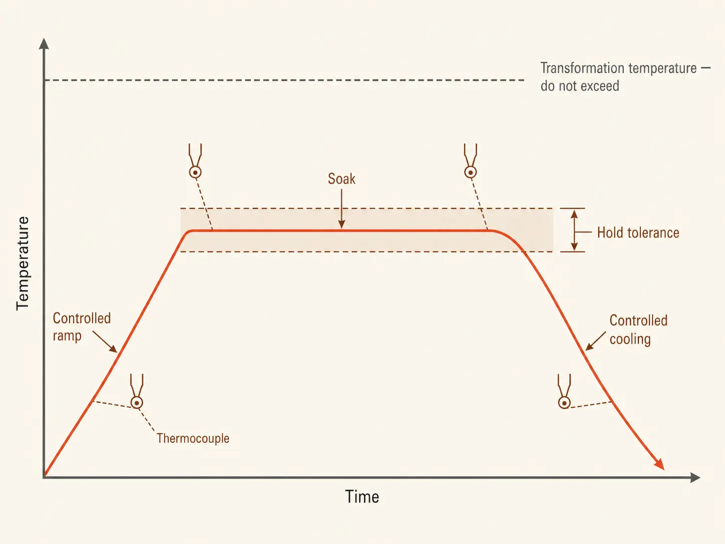
Welding, machining, forming, and thermal cutting all lock stress into metal. Stress relieving discharges it: the part is raised to a defined temperature window below the transformation point, held there for a specified soak, then cooled at a controlled rate. For carbon steels, that window typically sits at 550–650°C, with soak times around one hour per 25 mm of section thickness. Nothing melts, nothing rehardens — the metal simply gets warm enough for the locked-in stress to relax.
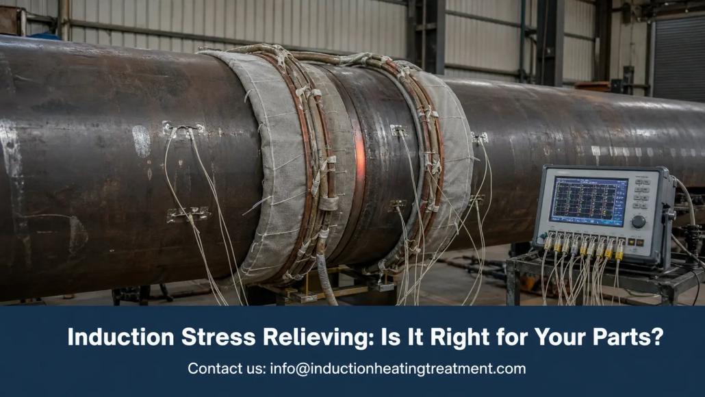
Induction does this with a coil or flexible heating cable around the target zone. The electromagnetic field generates heat inside the workpiece itself, in a defined band around the weld or critical section — the rest of the part stays out of the process entirely.
The temperature territory sits close to high-temperature tempering, and the hardware overlaps — an induction tempering system runs the same subcritical range. The difference is intent: tempering adjusts hardness after quenching; stress relieving discharges stress from welding, machining, or repair. Both belong to the same family of induction heat treatment systems.
2. Induction vs Furnace Stress Relieving
Both methods produce acceptable results when properly applied. The question is what you pay in handling, time, and energy to get there.
| Factor | Induction | Furnace |
|---|---|---|
| Heated zone | A defined local band | The entire part or batch |
| Part handling | Equipment comes to the part | Part goes to the furnace — cranes, carts, waiting |
| Heat-up speed | Fast — heat is generated in the metal | Slow — chamber and load climb together |
| Energy use | Heats kilograms | Heats the load, the fixtures, and the furnace |
| Batch work | One zone at a time | Strong for many small parts at once |
| Documentation | Per-weld temperature records | Per-load chamber records |
The furnace keeps its place when the specification demands full-body temperature uniformity, or when hundreds of small parts run as a batch. If the component fits an existing furnace and the schedule tolerates the queue, the furnace is the simpler buy.
Induction takes over when the code accepts a local soak band around the weld, when the part is too big or too awkward to move, or when furnace availability is the bottleneck. A pipe shop waiting two days for furnace space pays for that wait on every spool.
The traditional alternative for local PWHT is resistance blanket heating. Induction heats faster and generates energy in the pipe wall itself instead of soaking it through from a surface pad — the induction vs resistance heating comparison covers the mechanics.
3. Where It Earns Its Place: PWHT and Pipe Work
Post weld heat treatment is the biggest single use for induction stress relieving equipment. The recurring targets:
— Pipe girth welds and refinery or power plant piping
— Pressure vessel welds, flanges, and nozzles
— Boiler components
— Structural weldments and heavy equipment frames
— Large shafts, gear blanks, and castings before finish machining or after repair
Pipe is the friendliest geometry the process has. The cable wraps the weld, insulation goes over the top, thermocouples sit in the soak band, and the whole arrangement repeats on the next joint. Shops running similar diameters day after day store the recipe — coil layout, ramp, soak, alarms — and every shift runs the same cycle.
In shipyards, power plants, and pipeline work, the part is not going anywhere. Portable induction heaters with cable-style inductors bring the process to the weld, on a platform or in a trench, wherever the joint happens to be.
Machined components are the quieter use case. Rough machining and repair welding leave stress that shows up later as movement on the finish-machining table — the stress was always there, you just met it late. A localized cycle on the critical region before finishing keeps the geometry where the drawing says it belongs.
4. Sizing the System
The sizing questions match any induction heat treatment purchase, and each one has its own guide on this site. The stress-relieving-specific version, in brief:
Material and temperature. The window and soak come from the welding procedure specification, the code, or the customer — never from the equipment. Overshooting past transformation temperature changes the metallurgy you were trying to protect; undershooting leaves the stress in place. Nail down grade, wall thickness, window, soak, and ramp limits before any supplier conversation.
Power. Size on the heated mass, not the part mass — a local band on a 5-tonne vessel is still only a band. Undersized power stretches the ramp and lets heat bleed past the soak band. The power selection guide covers the math; a bench trial with a real part beats every estimate.
Frequency. Thick sections take lower frequency for deeper current penetration and even through-heating. Get it wrong on heavy weldments and you build temperature gradients the controller cannot fix. Frequency mechanics here.
Coil and cable. Coil geometry decides uniformity. Pipes wrap cleanly; irregular fabrications and heavy section changes need custom inductors, extra insulation, or staged heating — review the drawings early.
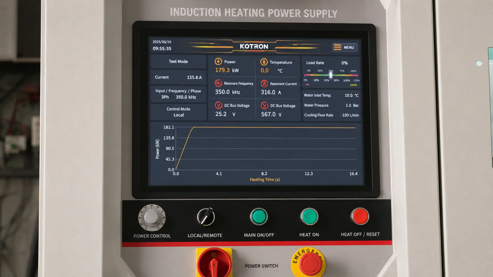
Cooling. The power supply, leads, and cables run water-cooled, and duty cycle lives or dies on the cooling system keeping up. A soak cycle is hours long — evaluate the full cooling package, flow to filtration, before signing anything.
5. Controls, Thermocouples, and Documentation
A stress relieving cycle is a contract: reach the window, hold it inside tolerance, cool at the specified rate — and prove all three happened. This is where induction systems separate from each other, and it is the section of the spec sheet that deserves the most scrutiny.
The control package that does the job:
— Programmable ramp and soak profiles
— Multiple thermocouple inputs with over- and under-temperature alarms
— Power output driven by temperature feedback, closed-loop
— Recipe storage for repeat jobs
— Automatic logging of time, temperature, and power for the full cycle
The controller only knows what the thermocouple tells it. A sensor placed too far from the weld, poorly attached, or sitting under a gap in the insulation feeds the controller the wrong number — and the system then holds that wrong number with perfect discipline. Procedure development must verify sensor locations; thick sections and critical welds take multiple thermocouples across the soak band to confirm uniformity.
For audited or code work, the recorded curve is the deliverable as much as the heat itself. A system that logs the full cycle automatically turns hours of manual chart-keeping into a file attached to the weld record.
6. Before You Request a Quote
System sizing is only as good as the data behind it. Walk in with these numbers and the quote means something; walk in without them and everyone is guessing.
| Parameter | Why It Matters |
|---|---|
| Material grade and wall thickness | Sets temperature window, frequency, and power |
| Target temperature and soak time | Comes from the WPS, code, or customer spec |
| Soak band width | Drives coil or cable choice and insulation coverage |
| Cycles per shift | Separates a portable unit from a production system |
| Available plant power | Limits the power supply options before anything else does |
| Field or shop conditions | Decides portability, cooling, and ruggedness |
| Documentation requirement | Determines the control and recording package |
Remember the power supply is half the purchase. The working system includes cables or coils, an output transformer, water-cooled leads, a chiller, thermocouples and a recorder, insulation blankets, and fixtures. A robust power supply feeding poorly made cables and one badly placed thermocouple produces out-of-spec welds with clean-looking paperwork — the worst failure mode there is.
Match automation to the work. Repeated similar joints reward automatic recipes and locked settings; one-off repair jobs reward portability and fast setup. And before the purchase order, check the boring list: spare parts, cable and coil repair options, cooling maintenance, training, remote support. A cheap system that cannot hold the procedure is the most expensive thing in the shop.
Key Takeaway
Induction stress relieving earns its place where the stress is local and the part is hard to move — weld bands, pipe joints, heavy fabrications — heating kilograms instead of tonnes and recording every degree of the cycle. Spec the system from the procedure outward: temperature window, soak band, and thermocouple layout first, then power, frequency, and coil. The furnace still wins on full-body uniformity and batch work; everywhere else, bringing the heat to the part is the shorter path.
FAQ
Q: Can induction be used for code PWHT?
A: Yes, when the code or welding procedure permits local heating of the weld band — and for pipe girth welds it usually does. The system has to hold the specified window with thermocouple feedback, respect ramp and cooling limits, and record the full cycle for the weld file.
Q: What temperature does stress relieving use?
A: For carbon steels, typically 550–650°C — below the transformation temperature — held around one hour per 25 mm of thickness. Alloy and stainless grades have their own windows, defined by the material spec or WPS.
Q: Is induction or a furnace better for stress relieving?
A: Furnace for full-body uniformity and batches of small parts. Induction for local weld bands, large or immovable parts, and jobs where furnace queue time costs more than the treatment. The specification decides — confirm local PWHT is permitted before comparing prices.
Put Your Stress Relieving Procedure in Front of an Engineer
Bring the WPS, the pipe sizes, and the documentation requirement. We will tell you whether induction fits the procedure — and size the power, cables, and controls if it does.


