
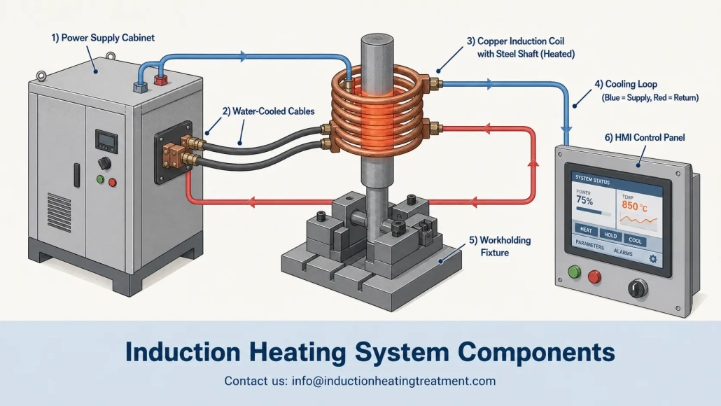
Components of an Induction Heating System: A Practical Explanation for First-Time Buyers
Buying your first induction heating system means you will be reviewing a detailed quotation full of induction heating system components whose specifications you may never have defined before — power supply, coil, cooling package, workholding fixture, controls, and sensors. Each item affects the next. If you overlook the details of a single component, you may end up with a system that works, but never truly works properly.
This guide was written for engineers and purchasing teams who need to understand what each component in an induction heating system does, which specifications matter, and where first-time buyers often make mistakes. This is not a catalog. Rather, it is a practical breakdown of the six components that determine whether your induction heating equipment delivers repeatable results or becomes an expensive lesson.
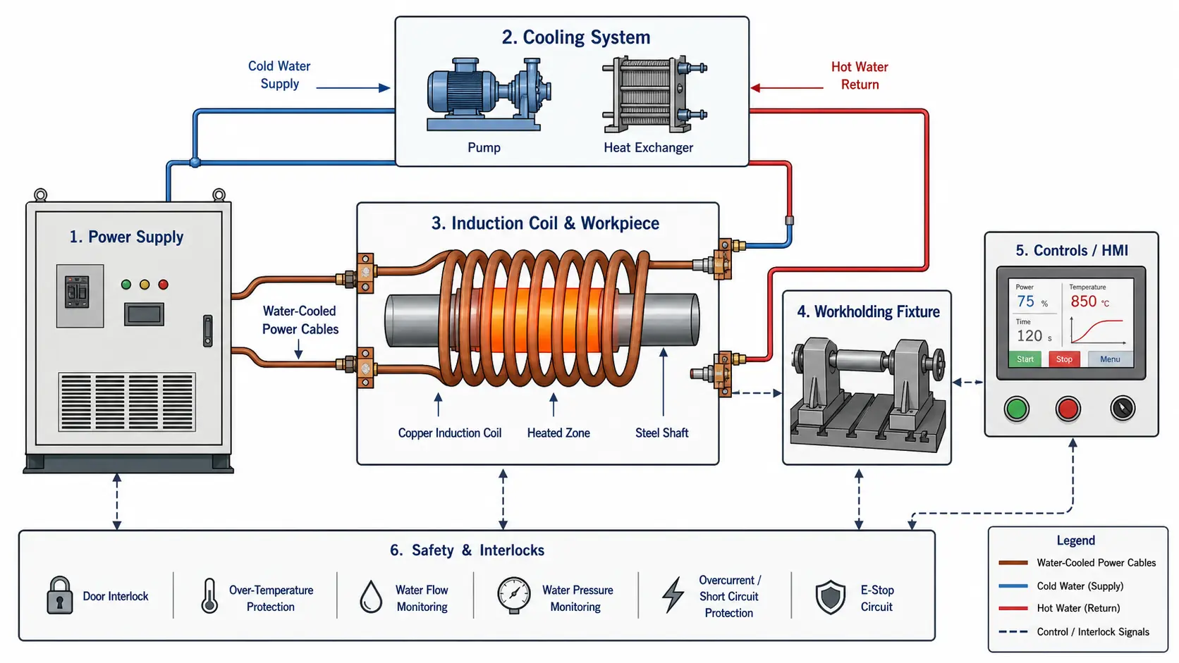
Start here: Six questions you should answer first
1. What exactly are you heating? Material and grade are critical — steel responds to induction differently than aluminum or brass. If you get this wrong, your frequency selection will be unsuitable from the start.
2. Which area needs to be heated? A small brazing joint, a bearing seat, or the entire cross-section of a metal bar — each case requires a different coil design and a different power level.
3. To what temperature, and how quickly? 200°C for shrink fitting requires a completely different system than 950°C for hardening. Temperature and heating rate determine everything that follows.
4. How many parts per hour? Five parts per day versus two parts per minute — the duty cycle changes, and with it the sizing of the cooling system and power supply.
5. Who will operate the system? An operator using a foot pedal needs a different workholding fixture, control setup, and safety design than a robot in an automated line.
6. What happens if the temperature deviates by 5%? If the answer is “scrap,” you need closed-loop control and data acquisition. If it is “not a major problem,” a validated time-power recipe may be sufficient.
| Component | Typical range | Risk indicator | Consequence |
|---|---|---|---|
| Power supply | 5–300 kW, 1–400 kHz depending on workpiece size and process | The supplier offers a kW rating without requesting the workpiece drawing or your cycle time | Unsuitable frequency = slow heating or incorrect temperature profile; insufficient power = operators run the system beyond its rated values |
| Induction coil | Designed for each workpiece; coupling gap typically 1–5 mm; copper tube or machined | “We use only one standard coil” for a production process | Uneven heating, low efficiency, coil burnout within a few days after commissioning |
| Cooling system | Closed-loop system, 20–50% reserve above the thermal rated load specified in kW; conductivity <10 µS/cm | Designed for average operation instead of peak load; use of untreated plant water | Sporadic downtime on hot days, mineral deposits in the coil channels, damage to the power supply |
| Workholding and motion | From manual fixture to servo control; non-conductive materials within 3× coil diameter | Placing metallic fixture elements near the coil; not checking positioning repeatability | Uncontrolled heating of the fixture, variation between workpieces that cannot be corrected by any power setting |
| Controls and sensors | PLC + HMI with recipe storage; pyrometer or thermal imaging camera; data acquisition for critical workpieces | No recipe storage; “the operator knows the settings”; no option for temperature verification | Operator-dependent quality, unvalidated process, failure during audit or customer qualification |
| Safety and integration | Flow + temperature interlocks on every cooled circuit; components from one engineering team | Components from more than 3 suppliers without a system integrator; no cooling interlock | Delays during commissioning, mutual blame in warranty issues, system damage due to undetected loss of cooling |
1. Power supply: the heart of the system
The power supply converts incoming mains power — typically 380–480 V, three-phase in industrial environments — into high-frequency alternating current that drives the induction coil. In most induction heating systems, it is the most expensive individual component and also determines the performance limit for everything that follows.
When engineers review a power supply data sheet, the first two values they look for are output power in kilowatts and frequency in kilohertz. Both are important. But they do not show the full picture — and relying only on these two numbers is one of the most common specification mistakes made by first-time buyers.
Key specifications that should be checked before purchase:
— Rated output power (kW) and whether it applies to continuous or intermittent operation
— Operating frequency or frequency range (kHz) — fixed or adjustable
— Duty cycle at your production rate, not just the value on the nameplate
— Input voltage, number of phases, and required connection current
— Load-matching capability — how efficiently it handles changes in coil and workpiece impedance
— Type of power control — voltage, phase angle, or digital DSP control
— Cooling requirements (water flow rate and inlet temperature range)
— Communication interface — discrete I/O, fieldbus, or Ethernet for factory integration
— Fault diagnostics and service accessibility — can your maintenance team access the components it needs to access?
Selecting power does not mean simply buying the highest kW rating your budget allows. An oversized power supply adds cost, takes up floor space, and may struggle to provide stable low power for sensitive processes. An undersized power supply, on the other hand, leads to long cycle times, encourages operators to run the system beyond its rated values, and delivers inconsistent results — especially with larger workpieces or high-output lines. For deeper insight into matching power to your process, read Power selection for induction heating.
Why frequency matters for your workpiece
Frequency determines how deeply the induced current penetrates into the workpiece — in other words, the reference depth at which around 87% of the heat is generated. Low frequencies (1–10 kHz) enable deeper current penetration, which is beneficial for through-heating large bars, metal blocks, or thick-walled tubes. Higher frequencies (100–400 kHz), by contrast, concentrate heat near the surface — essential for shallow case hardening, brazing small joints, or heating thin cross sections without overheating the core.
A system with the wrong frequency can still heat the part. However, it does so slowly, with low efficiency, or with an incorrect heat pattern — and operators spend their shifts compensating for a decision that was already made during the ordering phase. Learn more in our guide to frequency selection for induction heating.
2. Induction coil: Where precision is created
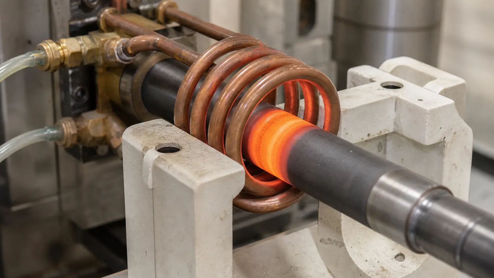
The induction coil is the component where electromagnetic energy is converted into heat in your workpiece. A well-designed coil delivers the right heat pattern with the right efficiency, cycle after cycle. A poorly engineered coil wastes energy, produces uneven heating, and fails prematurely — sometimes just a few days after commissioning.
Most industrial coils are made from copper tubing or machined copper conductors — and are hollow so that cooling water can flow through them. The coil acts both as an electrical conductor and as a heat exchanger. It operates at the interface of high current, high temperature, and mechanical stress from loading and unloading parts. When the performance of an induction heating system falls short of expectations, the coil is usually the first point to check.
Common coil types for production environments:
— Single-turn coils — the simplest design, used for localized heating of small areas
— Multi-turn helical coils — a common basic design for round bars, shafts, and tubes
— Pancake coils — flat spirals used to heat end faces, ends, or flat surfaces
— Channel coils — shaped channel for continuous heating of wires or strips
— Hairpin coils — U-shaped, for heating between two legs, often used in brazing
— Inner diameter coils (ID) — for heating inside bores or cavities
— Scan hardening inductors — narrow single turn with integrated cooling for progressive hardening
— Custom-shaped coils — designed according to the specific part geometry to ensure uniform heating
— Brazing coils with flux concentrators — focus the magnetic field onto a defined joint area
The coil is not an off-the-shelf product. In any process that goes beyond simple heating of a bar end or occasional laboratory use, a custom-designed coil often pays for itself within a few weeks through faster cycles, less scrap, and longer coil life. Treat the coil as part of the process — not as an accessory you order from a catalog after the power supply has arrived.
Coupling distance: the gap that determines efficiency
The distance between the coil and the workpiece — known as the coupling distance — directly controls the efficiency of energy transfer from the coil to the part. A larger gap means that more magnetic field lines do not pass through the workpiece and more energy returns to the power supply as reactive power. A smaller gap improves coupling but leaves less room for part dimensional tolerances, thermal expansion, and mechanical clearance.
In production, the fixture must hold the part at a consistent coupling distance in every cycle. A 1 mm deviation in part position can lead to a measurable difference in the heating pattern, especially at higher frequencies or in localized heating applications. If operators manually place parts into the coil by eye, variation should be expected — regardless of how good the power supply is.
3. Cooling: the component whose required size most buyers underestimate
Every component in an induction heating system that carries current generates heat — the power supply, the output transformer, the busbars, and especially the coil. Without sufficient cooling, the unit shuts down due to protective functions, operates at reduced power, or fails. The cooling system is not supporting accessory. It is an essential part that carries the process load, and the component whose sizing first-time buyers often misjudge.
Most industrial systems use closed-loop water cooling. A pump circulates treated water through the power supply and the coil and then through a heat exchanger or chiller to remove the absorbed heat. Cooling demand increases with power level, duty cycle, production environment temperature, and coil design — a tightly coupled coil operating at high current and 100% duty cycle requires significantly more cooling than a coil with greater coupling distance operated in short batches.
What a complete cooling circuit includes:
— Pump sized appropriately for the required flow rate and system pressure drop
— Heat exchanger (air-to-water or water-to-water) or mechanical chiller
— Reservoir with sufficient capacity as a thermal buffer
— Flow sensors and pressure gauges on each cooled circuit
— Temperature sensors at the inlet and outlet of critical components
— Filters or strainers to capture contaminants before they reach the narrow coil channels
— Conductivity control — monitors water quality and triggers maintenance actions
— Hoses, manifolds, and quick couplings rated for pressure and temperature
Water quality is not a minor detail. Untreated plant water contains dissolved minerals that deposit on hot copper surfaces, cause the channels to corrode, clog narrow coil passages, and reduce flow over time.
A closed loop with treated water — deionized or distilled, at conductivity below 10 µS/cm — costs more initially, but prevents most cooling-related failures. For a complete explanation, see our guide to water cooling systems for induction heating. For low-power processes or mobile applications, air-cooled systems eliminate the water circuit completely, though at the expense of maximum power and continuous-duty operation.
Cooling interlocks are low-cost protection
Flow switches and temperature sensors on each cooling circuit protect your equipment from damage. If water flow drops or outlet temperature exceeds a safe setpoint, the system must trigger an alarm or shut down before damage occurs. These interlocks are not optional — especially in automated cells where no operator is monitoring the thermometer. A $200 flow switch can prevent a $15,000 power supply repair.
4. Workholding & motion: Why identical parts heat differently
If the workpiece is not in the same position relative to the coil in every cycle, the heating result is not the same — even if the power supply, coil, and cooling are perfect. Workholding turns an induction heating process from an “operator skill” into “machine-capable repeatability.” It is the difference between parts that pass inspection and parts that go back for rework.
The appropriate workholding method depends on part geometry, cycle time, loading method, and how tight the required process tolerances are. A simple manual locating nest may be perfectly sufficient for a low-volume brazing station. In a high-volume hardening line producing safety-critical components, however, a servo-controlled rotary fixture with part-presence detection may be required.
Common methods for workholding and handling:
— Manual fixtures — the operator positions the workpiece; the simplest and most cost-effective solution
— Pneumatic fixtures — consistent clamping force and fast release
— Rotary tables — multi-station for parallel loading-heating-unloading
— Indexing machines — transport in a fixed sequence between stations
— Servo-driven slides — programmable position, speed, and dwell time for scanning processes
— Linear transfer systems — transfer beam or belt for inline production flow
— Pick-and-place systems — for small parts at high speeds
— Robot loading — flexible positioning for complex geometries or mixed part numbers
Fixture material selection matters more than it seems
Any conductive material near the induction coil can absorb energy, overheat, distort the magnetic field, or reduce efficiency. Fixtures near the coil are commonly made from ceramics, fiberglass-reinforced composites, austenitic stainless steel (low magnetic permeability at temperature), or water-cooled copper. The wrong material choice can turn the fixture into an unintended secondary heating element — drawing power away from the workpiece and creating a safety risk.
Motion as a process variable, not just material handling
Some applications require controlled relative motion between the coil and the workpiece. Scan hardening is the classic example: the coil and quench head move along a shaft or gear at a programmed speed, producing a uniform hardened layer.
Motion speed, workpiece rotation, power level, and quench timing all work together. If one of these parameters is changed without adjusting the others, the metallurgical result changes. In such applications, the motion system is part of the heat-treating process — not a separate material handling function.
5. Controls and sensors: Turning operating recipes into repeatability
Modern controls for induction heating go far beyond an on/off switch and a timer. PLC-based systems with HMI touchscreens control power ramps, heating time, frequency selection, workpiece rotation, feed speed, quench timing, and cooling status — all stored as operating recipes that can be selected by part number. For the production manager, that means the difference between “the operator who knows how this job runs” and “any trained operator can run this job.”
What induction heating controls typically manage:
— Power level setpoint and ramp rate (soft start to avoid thermal shock)
— Heating time and hold time with 0.1-second accuracy
— Frequency selection or automatic tuning to match coil impedance
— Coil or station selection in multi-coil systems
— Workpiece rotation speed and direction
— Feed speed and stroke length for progressive processes
— Quench delay, flow, and duration
— Cooling water flow and temperature monitoring with alarm limits
— Storage and recall of operating recipes by part number
— Alarm history and fault logging for maintenance diagnostics
— Production count and cycle time tracking
The fundamental decision is how much control your process actually needs — not how many features the supplier can list.
A simple manual brazing station may only need power, time, and a foot pedal. An automated hardening cell producing safety-critical drivetrain parts, however, may require closed-loop temperature control, recipe management with access levels, data acquisition for every cycle, and traceability down to individual part serial numbers. Match the control systems to the process — not to the data sheet.
Match the level of control complexity to the process risk. More features add cost, training requirements, and potential sources of error. The right control system is the simplest system that reliably keeps your process within specification.
Temperature monitoring: the measurement that confuses new buyers
Measuring part temperature during induction heating is not as simple as inserting a thermocouple. Surface condition, changing emissivity from part to part, steam or smoke in the heating-zone area, workpiece movement, and restricted optical access through the coil all affect sensor accuracy.
Common temperature monitoring options, from the simplest to the most capable:
— Infrared pyrometers — non-contact, fast response, but dependent on emissivity; they must be optically aligned correctly
— Thermal imaging cameras — full-area temperature map, useful for checking the heating pattern and setup
— Thermocouples — contact measurement, accurate, but slow to respond and sensitive to mounting position
— Post-process hardness testing and metallurgical cross-section examination — the reference standard, not real-time, but critical for verification
For many production processes, the practical path is simpler: verify a fixed recipe of time, power, and motion during initial commissioning through metallurgical testing, and then monitor the process variables that keep that recipe under control.
Chasing an instantaneous temperature value that may be unreliable under production conditions is often riskier than stabilizing a verified recipe. Close the loop on what you can measure repeatably. And stabilize everything else.
6. System integration: Why buying components separately fails
Here is the mistake that often occurs during first purchases of induction heating system components: buying a power supply from one supplier, a coil from another, assembling the cooling from plant infrastructure, building a fixture in-house, and then expecting everything to work as a single system on day one.
That rarely happens — or at least not without weeks of troubleshooting and rework that consume the money you thought you had saved by sourcing separately.
These components are linked in ways that individual data sheets do not reveal. The power supply’s frequency range limits the coil design. The coil design determines cooling demand. Cooling capacity limits the maximum duty cycle. The fixture controls coupling consistency, which directly affects how much power the process actually absorbs. And the controls must communicate with the power supply, motion system, and sensors within the same timing window.
When components are specified in isolation from one another, the gaps between them become your commissioning problem — and no warranty from any party covers the statement: “The other party’s part did not work with our part.”
Five specification mistakes that happen again and again:
— Buying kW without testing the process. A 50-kW power supply can heat a 50 mm diameter bar. But can it heat your bar, at the rate you need and with the required temperature uniformity? The power rating alone does not answer that question. Whether those kilowatts are converted into usable heat or wasted electricity depends entirely on coil design, frequency, coupling, and fixture repeatability.
— Treating the coil like a standard catalog part. Some simple applications work with standard coils. Most production processes, however, do not — or they work, but slowly and with large process variation. An unsuitable coil leads to uneven heating, low electrical efficiency, long cycle times, or premature coil failure. In most cases, the cost of a custom coil is lower than the cost of downtime and scrap caused by using an unsuitable coil.
— Underestimating cooling requirements. Cooling problems often appear as sporadic stoppages, lower output at high duty cycles, coil damage, or power supply fault codes that seem unrelated to cooling. Cooling capacity must be designed for peak demand at maximum duty cycle, not average demand — and it should include reserve for high ambient temperature days, aged heat exchangers, and future production increases.
— Ignoring variation in incoming parts. Alternative material grades, changes in surface condition, mass variations within a batch, and tolerances in part positioning all affect the heating result. If your incoming parts vary significantly, your system must include the required controls, workholding, or process limits to manage that variation — or the specifications for incoming parts must be tightened.
— Separating automation from process design. Automation must support the heating process and must not be limited only to moving the parts. Cycle time, positioning accuracy, rotational speed, quench delivery, and sensor accessibility must be designed to match the induction heating cycle. If automation is added only after the heating process has been defined, it usually forces compromises that later become visible in the quality data.
Define the process before you specify the equipment
Before you send an RFQ, define the technical details that will later determine every component decision — part material and grade, heating zone and its geometry, starting and target temperature, required heating time, production rate, case depth or joint design if applicable, available electrical service and cooling water, footprint, operator skill level, and quality documentation requirements.
A brazing system and a hardening system may use the same power supply model number, but the coil, fixture, cooling requirements, control logic, and process validation steps are completely different. The more precisely you define the process at the beginning, the fewer surprises you will encounter during commissioning.
For general guidance on system specifications, see our article on selecting an induction hardening system. For process-specific considerations when joining is performed instead of heat treatment, our guide to induction brazing explains what changes.
How component priorities change depending on the application
The same six components remain important in every induction heating system, but their relative importance changes depending on the process. A brazing station prioritizes precision and accessibility of the joint. A hardening system prioritizes power density and integration of rapid cooling. Buying the right system means knowing which variables must be adjusted for your application.
| Application | Power Source Priority | Coil Priority | Cooling Requirements | Control Complexity |
|---|---|---|---|---|
| Copper and Soft Soldering | Medium kW power, higher frequency (100–400 kHz), precise control at low power | Centered magnetic flux, joint-specific geometry, operator access for feeding the filler metal | Low to medium | Low — time + power recipe, foot pedal or simple HMI |
| Induction Hardening | High power density, frequency matched to the case depth, fast heating rate | Scanning or single-shot with integrated quenching, tight coupling gap | High — continuous production, and quenching adds a thermal load | High — recipe + temperature + quench timing + motion + data acquisition |
| Forging / Billet Heating | High kW power, lower frequency (1–10 kHz) for through-section heating, high duty cycle | Multi-turn helix, robust for continuous feeding, uniform heat along the workpiece | Very high — near-continuous operation | Medium — temperature + feed rate + safety interlock with press or hammer |
| Shrink Fitting | Low to medium kW power, short cycle, low duty | Single turn or simple helix, fast workpiece changeover | Low | Low — time + power, often manual operation |
5 specification mistakes that keep coming up
— Buying kW without validating the process. A 50 kW power source can heat a 50 mm bar — but can it heat your bar at the rate you require and with your uniformity requirements?
— Treating the coil like a catalog item. The wrong coil wastes energy, creates scrap, and fails early. A custom-designed coil pays for itself within a few weeks.
— Sizing cooling for the average instead of the peak. Cooling failures happen on the hottest days and at the highest duty cycle. A safety margin is less expensive than a production stoppage.
— Ignoring variations in supplied parts. Material, surface, mass — if your parts vary, your system needs the necessary control or fixturing to compensate for those variations.
— Separating automation from process design. If you add automation only after the heating process has been defined, the compromises will show up clearly in your quality data.
Key Takeaway
Most induction heating problems do not start with a poor power supply. They start when a single induction heating system component is specified in isolation from the other components. The six core components — power supply, coil, cooling, workpiece fixture, controls, and system integration — must be treated as one engineered system, not as a shopping list.
If you define the process first and then match the components to it, the system components work together. If you buy components first and connect them later, you will spend your commissioning budget on troubleshooting and rework — and discover that the most expensive component is the one you did not examine thoroughly enough.
Q: Can I use the same power supply for brazing and hardening?
A: Sometimes, but not without changing the tooling and process parameters. Brazing typically requires lower power density, localized heating, and manual or semi-automatic part handling. Hardening, by contrast, often requires higher power density, controlled case depth, integrated quenching, and a more precise cycle time. A power supply with a sufficiently broad frequency and power range can support both processes, but the coil, fixture, cooling setup, and control recipes will each be different. Plan for two tooling sets — not a single machine that performs both processes without changeover.
Q: Is it worth paying more for a custom induction coil?
A: For any production process that goes beyond simply heating the end of a bar or occasional laboratory use: yes. A custom coil designed for your part geometry and specific heating objective typically pays for itself within a few weeks through faster cycle times, lower scrap rates, and longer coil life. Off-the-shelf standard coils work for general applications, but they rarely deliver the best performance for a specific production process. If your process runs more than a few hours per week, the coil is not the right place to save money.
Get an application-based system review
Share your part drawing, material, target temperature, and production rate with us. Our engineering team can help you evaluate the requirements for power, frequency, coil design, cooling, and automation for your process.


