
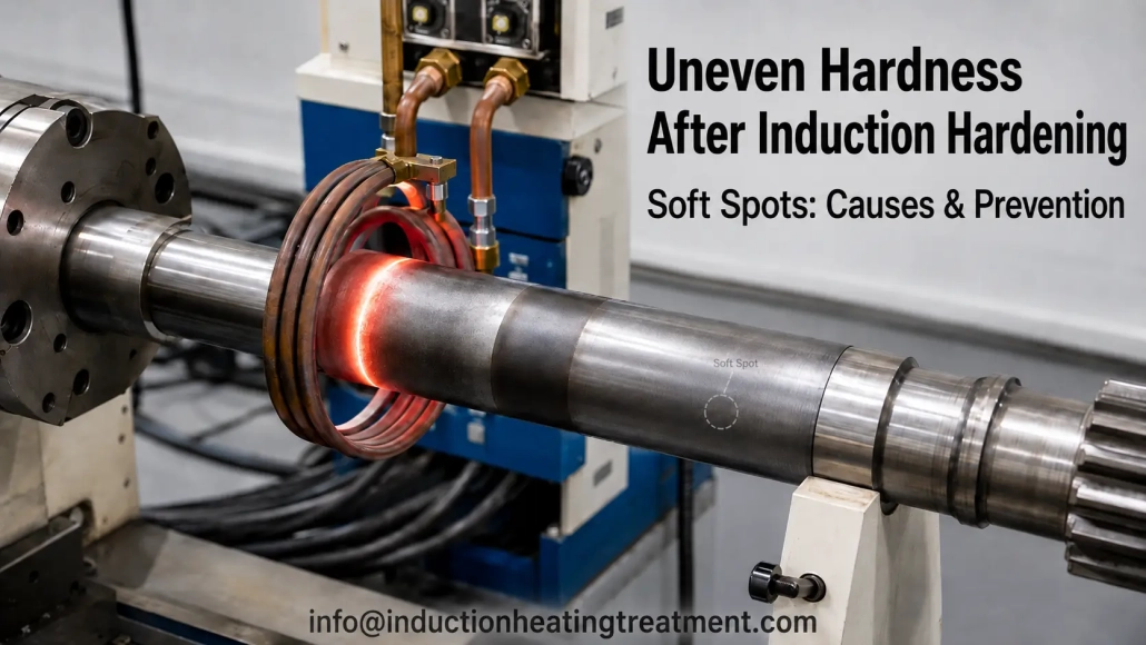
Uneven Hardness After Induction Hardening: Causes of Soft Spots and How to Prevent Them
Uneven hardness after induction hardening may appear as isolated soft spots, continuous soft bands, or a larger area where hardness falls below the specified level. For parts exposed to wear, contact stress or repeated loading, a locally soft area can become the first place where damage develops. The challenge is that very different problems can produce a similar hardness reading.
The cause may already exist in the material before heating. It may come from uneven induction heating, an incorrect relationship between the coil and the workpiece, unstable scanning or rotation, or poor quenching immediately after heating.
Simply increasing induction power is therefore not a reliable way to solve the problem. A better approach is to look at where the low-hardness area appears, whether the pattern repeats, and which part of the hardening process corresponds to that location.
1. Start With the Material and Surface Condition
Not every hardness problem begins with the induction hardening machine. The condition of the steel before hardening affects how it responds to rapid heating and cooling.
Uneven Starting Microstructure
Severe variation in the original microstructure can lead to an uneven hardening response. Possible problems include coarse or inconsistent grain structure, carbide segregation, localized carbide accumulation, large areas of free ferrite, or other significant differences in the starting structure.
During induction heating, the surface is heated rapidly. Austenite formation and carbide dissolution therefore take place within a relatively short thermal cycle. If the starting structure varies substantially from one area to another, the final hardened structure may also vary even when the machine settings remain unchanged. This becomes particularly worth investigating when the same process produces different results between material batches.
Surface Decarburization
Decarburization is another possible source of low surface hardness. If previous forging, rolling or heat treatment has left a decarburized layer on the workpiece, that surface contains less carbon than the material underneath. After induction hardening, the affected layer may fail to reach the expected hardness. Changing the induction power cannot restore carbon that has already been lost from the surface.
If decarburization is suspected, the surface condition should be checked and the affected layer removed by suitable machining or grinding before final hardening. Material grade, previous processing history and incoming surface condition should therefore be verified before assuming that every soft spot is an equipment problem.
2. Uneven or Insufficient Induction Heating
The required area must first be heated to a suitable austenitized condition before rapid cooling can produce the intended hardened structure. If one part of the surface receives insufficient heat, that area may remain softer after quenching. Possible causes include insufficient energy input, a heating time that is too short, unsuitable power distribution, inconsistent workpiece position, incorrect scan settings, or a change in the heating pattern caused by the part geometry.
A useful distinction needs to be made here.
A machine can deliver enough total power while still producing an uneven local heating pattern.
For example, increasing power may raise the temperature of most of the hardened area while a poorly coupled region continues to heat differently. This is one reason why low hardness should not automatically lead to a higher power setting.
The location of the soft area matters. If hardness becomes low only near a shoulder, diameter transition or another specific feature, the problem may be related more to local heat distribution than to the rated power of the machine.
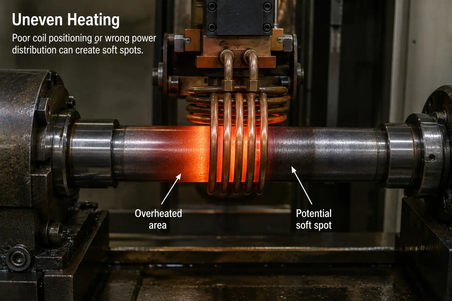
A localized soft spot can appear even when the surrounding hardness is within specification.
3. Check the Inductor, Workpiece Position and Part Geometry
In induction hardening, the relationship between the inductor and the workpiece has a direct effect on the heating pattern. Changes in coil geometry, coil position and coil-to-part gap can change how energy is distributed into the surface. This creates several possible sources of uneven heating: the workpiece is not centered in the inductor, the coil has moved from its original position, the inductor has been deformed or damaged, fixture wear has changed the workpiece position, workpiece runout changes the gap during rotation, replacement coils do not reproduce the original geometry accurately, or dimensional variation between parts changes the coupling condition.
For cylindrical components, a noticeably softer area on one side of the circumference is a good reason to inspect centering, runout and coil position before changing the heating recipe.
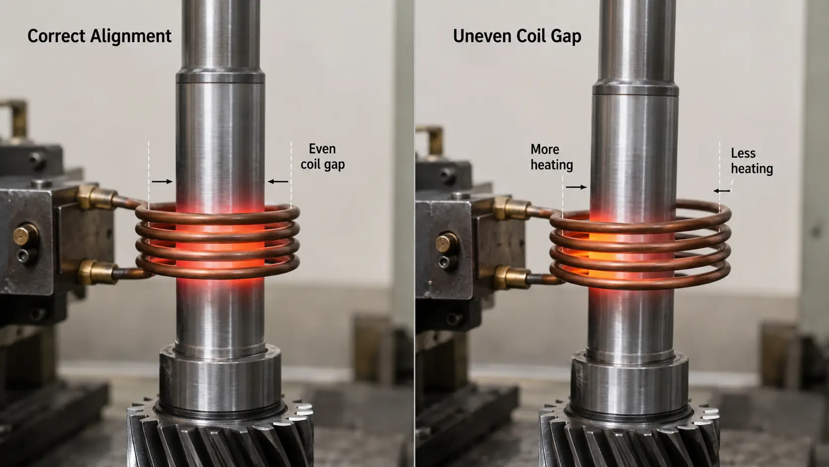
Correct alignment (left) versus an uneven coil gap (right) changes the heating pattern across the surface.
Geometry Cannot Be Ignored
Stepped shafts, shoulders, grooves, thin sections, sharp transitions and changes in diameter do not heat in exactly the same way as a simple uniform cylinder. The local thermal mass changes, and so does the electromagnetic relationship between the part and the coil. Cooling conditions may also change around these features.
A single fixed setting may therefore produce an acceptable result on one section of the workpiece but an undesirable result on another. Depending on the component, improving hardness uniformity may require changes to inductor geometry, coil position, heating sequence, power distribution, scanning strategy, or quench arrangement. The workpiece geometry is part of the hardening process, not just something placed inside the machine.
4. Scan Speed and Workpiece Rotation Can Affect Hardness Distribution
For scan hardening, the thermal cycle depends partly on the relative movement between the workpiece and the heating system. If movement changes, the heating condition can change along the hardened length. Possible issues include unstable scanning speed, incorrect programmed speed, acceleration or deceleration inside a critical hardening area, inconsistent scan start or stop positions, or mechanical movement that is not repeatable.
A hardness variation running along the scanning direction should therefore be compared with the actual machine movement. If the low-hardness area repeatedly appears at the same axial position, check what the machine is doing at that position rather than treating the defect as random.
Workpiece Rotation
Rotation is often used when a cylindrical component needs more uniform treatment around its circumference. Irregular rotation, slippage or mechanical instability can expose different areas of the surface to different heating conditions.
However, rotation should not be considered only during heating. It also affects the way the quenchant reaches the surface. The correct rotational condition therefore needs to work with both the induction heating and quenching stages. When hardness differs around the circumference, check whether the workpiece is rotating consistently, whether the part is centered, whether the coil gap changes during rotation, and whether the spray reaches the complete circumference correctly. These variables are often connected.
5. Uneven Quenching Is Another Major Cause of Soft Spots
A correctly heated surface can still remain soft if the cooling condition is inadequate. In induction hardening, quenching usually follows the heating stage very quickly. A local failure in cooling can therefore create a local hardness problem even when the heating pattern appears normal. Possible causes fall into two groups.
Supply problems — the quenchant does not reach the surface: insufficient quenchant flow, uneven spray distribution, blocked or partially blocked nozzles, or inadequate circulation.
Contact and medium problems — the quenchant reaches the surface but does not cool it evenly: contaminated quenchant, poor surface wetting, air or vapor interfering with liquid contact, unstable quenchant condition, or tooling or fixtures shielding part of the surface.
Simply seeing liquid coming from the spray system does not prove that the quench is uniform.
The important question is whether the complete required surface receives a sufficiently consistent cooling condition.
Quenchant Condition Changes Over Time
Cooling problems do not always appear when a process is first established. A production line may run correctly for a long period and later begin producing soft spots because spray holes become partially blocked, contamination builds up, filtration deteriorates, circulation changes, nozzle position moves, or quenchant temperature changes beyond the normal process condition.
When an established process suddenly begins producing uneven hardness, the cooling system deserves early inspection.
What About Vapor Film?
When a very hot surface comes into contact with liquid, vapor can temporarily interfere with direct contact between the quenchant and the metal. If this effect develops unevenly around the workpiece, cooling may also become uneven. Good circulation and an appropriate spray arrangement help reduce localized cooling differences.
The original heat-treatment practice of using more severe media such as brine in some carbon-steel applications should not be treated as a universal solution for induction hardening. A more aggressive quench can also increase the risk of distortion or cracking. The quenchant and cooling arrangement need to be selected for the actual steel, geometry and hardening requirement.
6. Use the Hardness Pattern to Narrow Down the Cause
When a part fails hardness inspection, the value itself is only part of the information. The shape and location of the low-hardness area can provide useful clues.
The shape and location of the low-hardness area tell you where to look first.
Consider several different situations. These patterns do not provide a final diagnosis by themselves, but they help determine where to start.
| Soft-Spot Pattern | Where to Look First |
|---|---|
| One small isolated soft spot | local spray failure · contamination · local surface condition · a localized material problem · an obstruction |
| One side of a shaft is softer | workpiece centering · coil-to-part gap · runout · coil deformation · rotation · circumferential spray coverage |
| A soft band runs along the workpiece | scanning movement · coil position · part geometry · spray arrangement · whether the pattern repeats |
| Hardness changes at scan start or end | scan start and stop positions · acceleration and deceleration · heating sequence · timing between heating and quenching |
| Entire hardened area too soft | material grade or condition · surface decarburization · insufficient heating · process settings · inadequate quenching |
For a broader look at the defect types behind these patterns, see our guide to common induction hardening defects.
7. A Practical Troubleshooting Sequence
Changing several parameters at once is one of the easiest ways to make troubleshooting more difficult. If the next workpiece passes, you may know that something helped, but not which change actually solved the problem. A more useful sequence is:
Map the Hardness
Record where each measurement was taken, not only the lowest value. Compare acceptable and unacceptable areas and determine whether the pattern is random or repeatable.
Check the Incoming Part
Confirm steel grade and material batch, previous heat-treatment condition where relevant, surface condition, possible decarburization, and abnormal microstructure if suspected. If the problem began with a change in material batch, investigate that change before rebuilding the process.
Inspect the Inductor and Fixture
Check coil shape, position and working gap, signs of deformation or damage, fixture condition, workpiece centering and runout. If the problem started after coil replacement or maintenance, compare the current setup with the previously successful one.
Review Machine Movement and Heating Parameters
Check heating time and power output, scan speed and scan position, workpiece rotation, and the start/stop sequence. Where process records are available, compare a known good cycle with a failed one.
Inspect the Quenching System
Check nozzle condition and spray pattern, quenchant flow, circulation and filtration, quenchant condition and temperature, and tooling interference. Check the spray where the soft area actually occurs.
Examine the Structure if the Cause Is Still Unclear
Hardness testing confirms that a difference exists, but it does not always explain the metallurgical cause. If necessary, section the affected area and examine the microstructure. This can help distinguish between insufficient transformation, poor quenching, decarburization and abnormal starting material. A traditional file test can still be useful as a quick shop-floor comparison, but treat it as a rough screening method rather than a substitute for specified hardness testing or metallographic examination.
8. How to Reduce the Risk of Uneven Hardness
There is no single machine adjustment that prevents every soft spot. Prevention has to address the complete process.
Material
Maintain reasonable consistency in steel grade and incoming material condition. Where necessary, check for abnormal microstructure and remove unacceptable decarburized surface layers before final hardening.
Induction Heating
Use an inductor suited to the actual workpiece geometry. Keep the relationship between the coil and the workpiece repeatable, paying particular attention after coil replacement, fixture maintenance or changes in part dimensions. Do not rely on power alone to correct an uneven heating pattern.
Machine Movement
Keep scan speed, positioning and workpiece rotation repeatable. For parts with multiple diameters or more complex geometry, review whether the movement and heating strategy need to change through different sections of the workpiece.
Quenching
Maintain the spray and cooling system as a process component, not just an auxiliary system. Check nozzle condition, spray coverage, circulation, filtration and quenchant condition regularly. A stable heating process cannot compensate for an unstable quench.
Inspection
Define where hardness should be measured. For troubleshooting, retain the location of the measurements instead of recording only a minimum and maximum value. Where possible, compare hardness patterns with machine positions, heating records and quenching zones — that makes it much easier to connect a defect with its physical cause.
Key Takeaway
Uneven hardness after induction hardening is best treated as a process investigation, not a single-parameter fix. The result depends on one chain working together:
Material → Surface Condition → Inductor and Geometry → Heating → Machine Movement → Quenching
When a soft spot appears, start with its location — isolated or continuous, one-sided, or following the scan — and connect that pattern to the physical cause before touching a setting.
Frequently Asked Questions
Click a question to expand the answer.
What causes soft spots after induction hardening?
There is no single universal cause. Soft spots may result from material or microstructure variation, surface decarburization, insufficient local heating, incorrect coil positioning, unstable scanning or rotation, or uneven quenching. The location and pattern of the soft area should be examined before adjusting the machine.
Can the induction coil cause uneven hardness?
Yes. Coil geometry, position and the gap between the coil and workpiece affect the heating distribution. If the part is off-center, the coil has been damaged, or a replacement coil differs from the original, the heating pattern can change.
Why is one side of a hardened shaft softer than the other?
Possible causes include off-center workpiece positioning, excessive runout, unequal coil-to-part gap, unstable rotation, and uneven spray coverage. Both the heating and quenching systems should be checked.
Should I increase induction power when the hardness is too low?
Not before identifying the likely cause. Higher power may help if the problem is insufficient heating. It will not correct decarburization, poor material, coil misalignment, blocked spray nozzles or an incorrect quenching condition. Increasing power without diagnosis may also overheat areas that were already acceptable.
Diagnosing a Recurring Soft Spot?
Send us your hardness map, material spec and a photo of the failed area. We will help you trace it to the coil, the scan movement or the quench.


