
Automatic Induction Hardening Machine for Powder Metallurgy Gears
Ⅰ. Automatic Gear Hardening Process
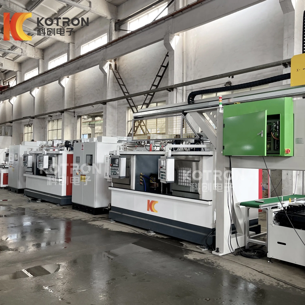
Built around the workpiece rather than a standard machine frame, this automatic gear induction hardening machine is available in 4-station and 6-station configurations. Gears transfer into the hardening area, position for induction heating, quench, and move through the full sequence automatically — no repeated manual handling. Inductor geometry, workholding, and station layout are adapted to the specific gear during engineering design rather than being locked to one standard arrangement.
Ⅱ. Automatic Multi-Station Gear Hardening System
For manufacturers that need repeatable induction hardening in continuous or batch production, a complete system can include:
Multi-Station Positioning
Induction Heating Unit
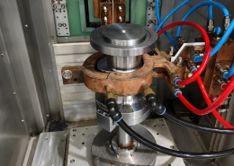
Customized Induction Coil
Quenching System
CNC / PLC Process Control
Induction Power Supply
Cooling System
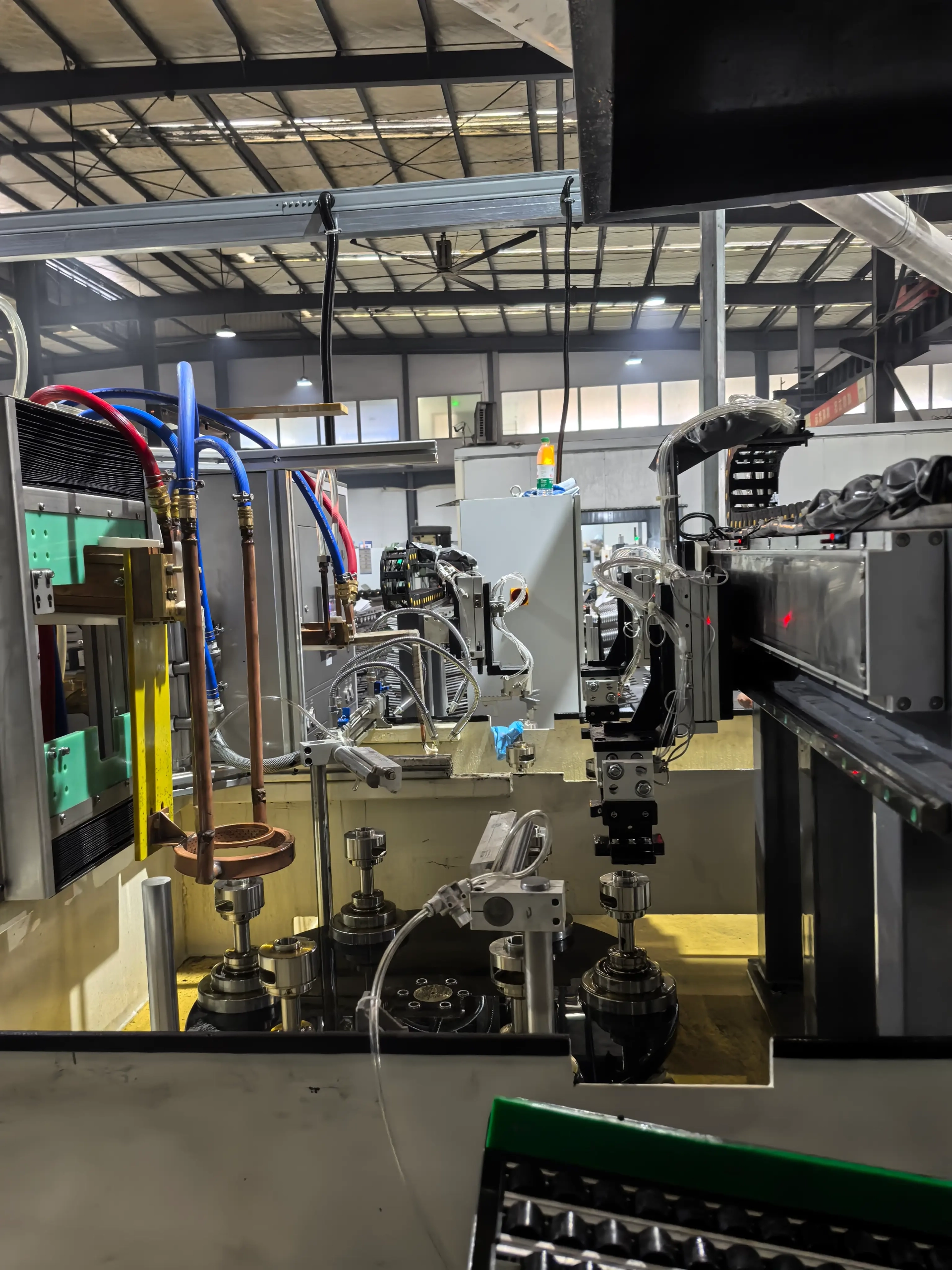
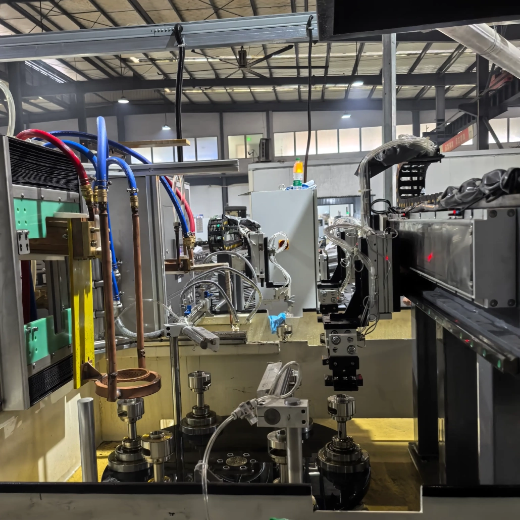
Gantry loading system
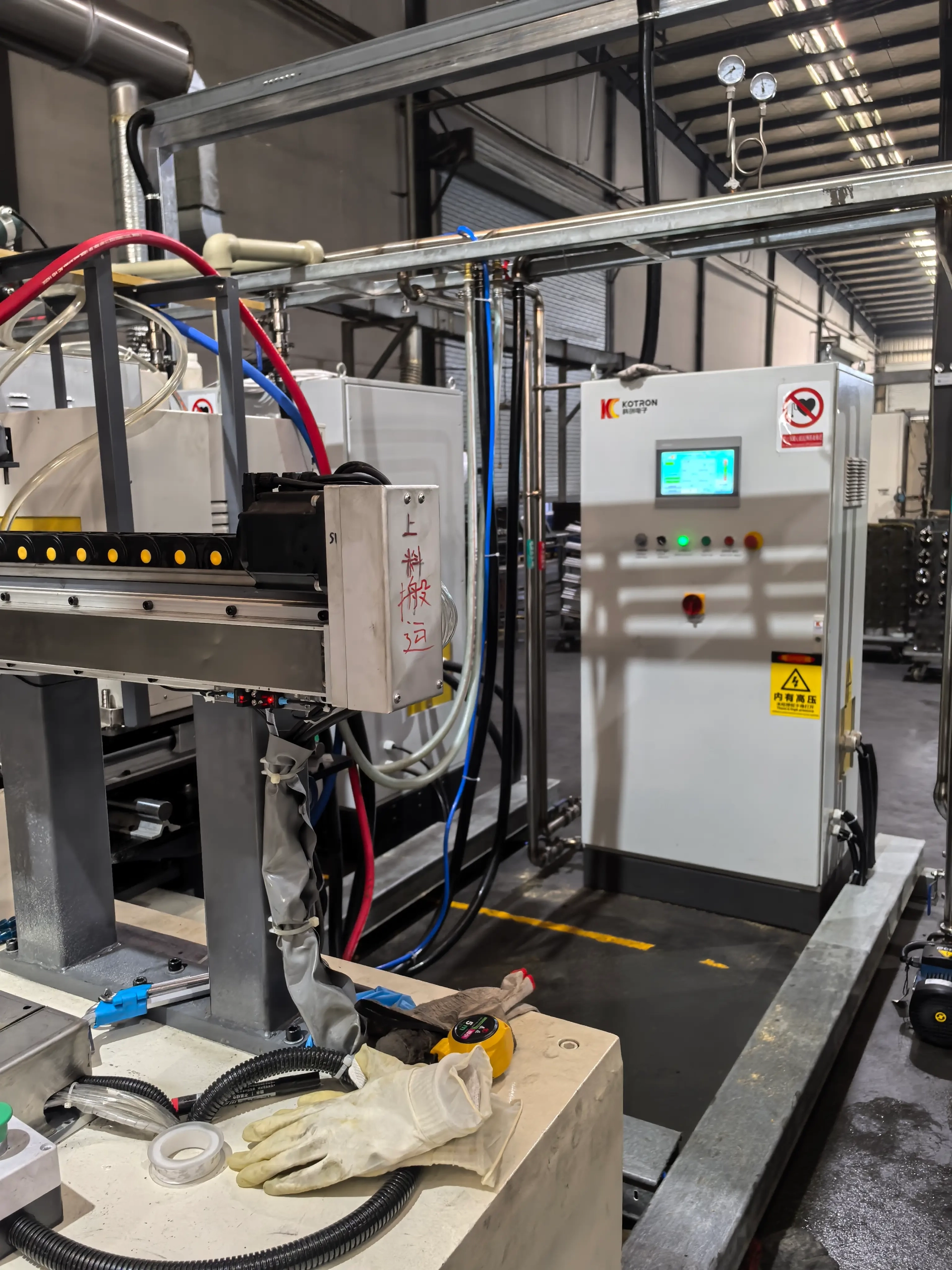
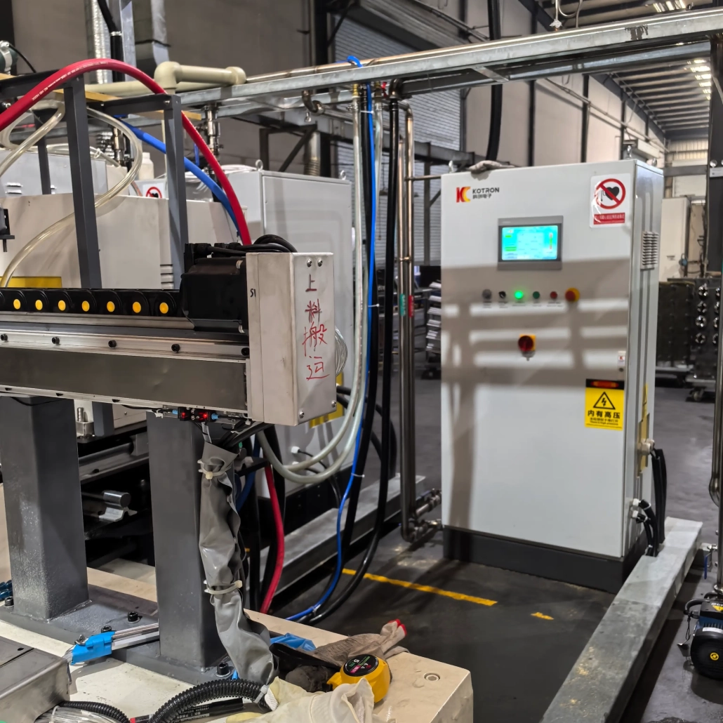
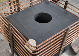
Induction power supply unit
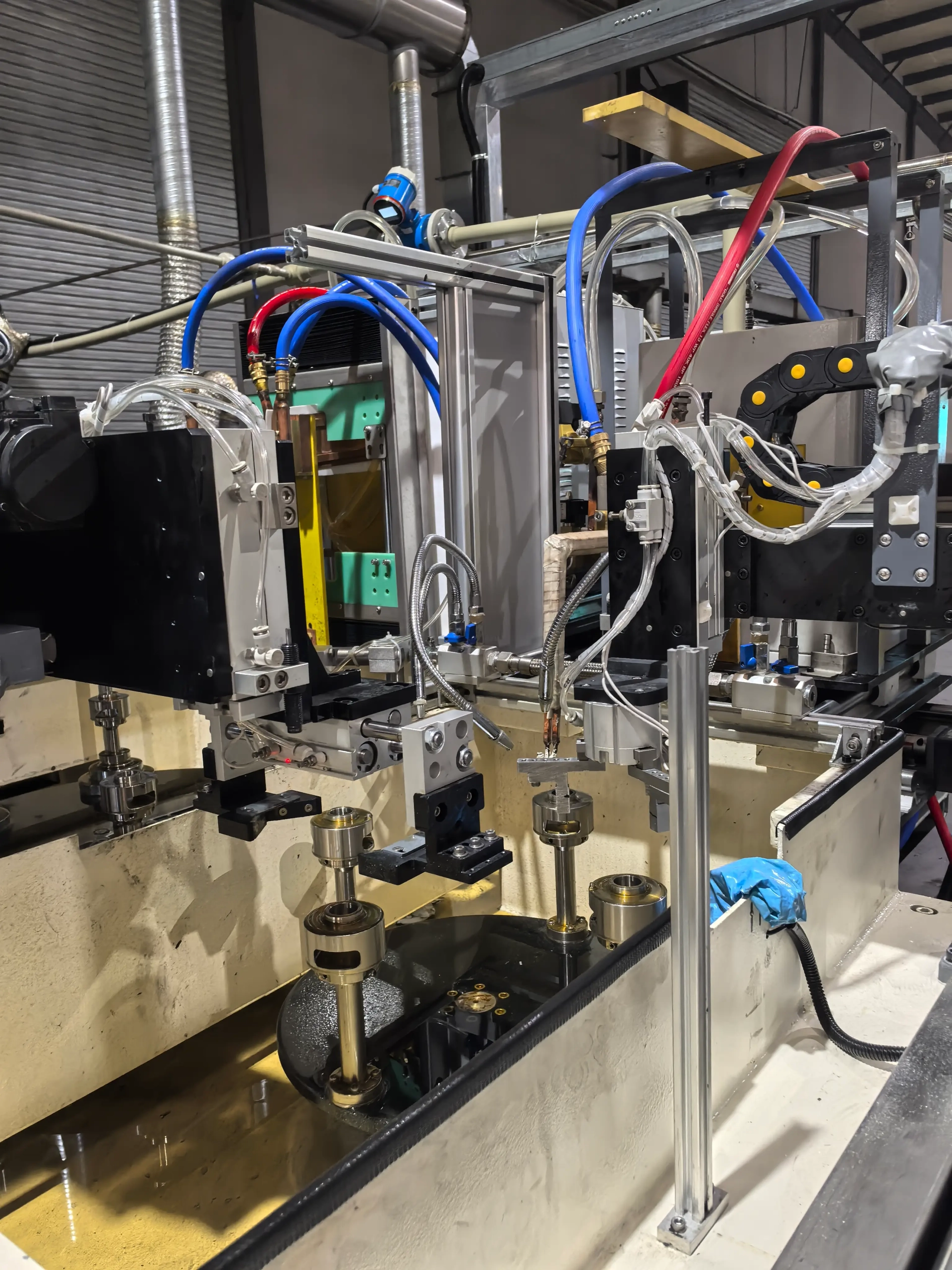
Sintered gear components
Automatic gantry loading keeps part transfer integrated with the hardening cycle and reduces manual work around the heating station.
Ⅲ. 4-Station and 6-Station Configurations
The machine is available in 4-station and 6-station versions. A four-station layout suits applications where the hardening sequence is relatively compact. Six-station machines provide more positions for separating loading, heating, quenching, cooling, or other process steps when production flow requires distinct stages.
The exact function of each station is determined during machine design — not pre-assigned from a standard template. Adding more stations does not automatically produce a better result. The correct configuration depends on the gear geometry, required heating cycle, and target production throughput.
Ⅳ. Automatic Loading and Hardening Process
A typical production sequence moves through six stages. On a multi-station machine, several gears occupy different stages simultaneously.
2. Positioning →
3. Induction Heating →
4. Quenching →
5. Transfer →
6. Unloading
The station layout, fixture movement, and loading method are configured around the actual gear and process requirements. No two gear designs share the same heating pattern, so the machine is engineered per application — not selected from a fixed catalogue layout.
Ⅴ. Induction Heating Power and Process Control
The induction power supply delivers controlled energy to the inductor during the hardening cycle. For gear applications, the result depends on more than rated power. Gear diameter, tooth geometry, material grade, required hardened area, heating time, and inductor design all influence the final hardness pattern and case depth.
Where equipped with IGBT power conversion and DSP digital control, heating parameters are regulated through the machine control system and stored for repeat production. Typical controllable items include:
| Parameter | What It Controls |
|---|---|
| Heating power | Energy delivered to the inductor during the hardening cycle |
| Heating time | Duration of energy application per part |
| Workpiece position | Part alignment relative to the inductor during heating |
| Quenching sequence | Timing, flow rate, and duration of quenchant delivery |
| Machine movement | Station indexing, part transfer, and gantry operation |
| Process recipes | Stored parameter sets for different gear part numbers |
Actual functions depend on the selected machine configuration.
Ⅵ. Powder Metallurgy Gear Hardening Applications
This system is configured for automatic hardening of powder metallurgy gears and sintered gear components. Depending on material and hardening requirements, a customized induction system can also be evaluated for other gear-type components.
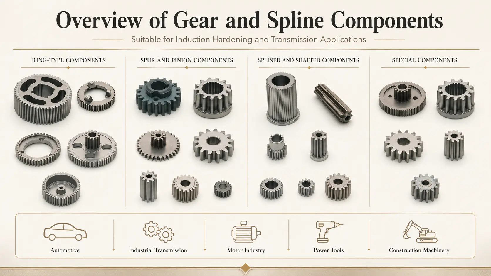 Depending on material and hardening requirements, a customized induction system can also be evaluated for spur gears, internal gears, spline gears, gear hubs, pinions, gear shafts, and ring-shaped gear components. Different gear structures require different inductors and workholding arrangements — the gear drawing and required hardened area should be reviewed before machine selection.
Ⅶ. Machine and Production Line Overview
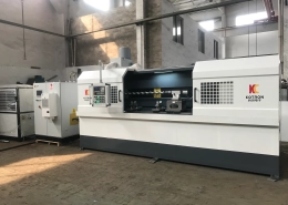
This video shows the complete machine in a non-working condition, including the hardening machine tool and induction power unit. It is useful for understanding the overall equipment arrangement, the gantry loading system, and the relationship between the mechanical station layout and the power supply cabinet.
Ⅷ. Technical Configuration
Because this equipment is built around the workpiece and production process, the main specifications are determined from the actual gear — not pre-selected from a standard datasheet.
| Item | Configuration |
|---|---|
| Machine Type | Automatic induction hardening machine |
| Station Options | 4 stations / 6 stations |
| Loading Method | Automatic gantry loading and unloading |
| Workpiece | Powder metallurgy gears and related gear parts |
| Induction Power | Selected according to workpiece and process |
| Frequency | Selected according to heating requirement |
| Inductor | Customized |
| Hardening Process | Configured according to required hardened area |
| Control System | CNC / PLC / DSP configuration according to machine design |
| Cooling System | Configured according to process requirements |
Ⅸ. Information Required for Machine Selection
To put together a proposal, you can share with us three things: the gear drawing, the material grade or specification, and the required hardened area. If you also have target hardness, layer depth requirements, production capacity, or factory power supply details, those help refine the recommendation — but the drawing is the right place to begin.
Ⅹ. FAQ
Can the same machine process different gears?
Possibly. Whether different gears can share one machine depends on their dimensions, fixtures, inductors, and hardening requirements. Changeover parts may be required — this is evaluated during the engineering review.
Should I choose a 4-station or 6-station machine?
The choice depends on the number of process steps, part handling requirements, and target production cycle time. It should be determined after reviewing the gear drawing and production requirement — not selected in advance from a spec sheet.
Is this machine limited to powder metallurgy gears?
No. This system is presented around a powder metallurgy gear application, but similar automatic induction hardening systems can be designed for wrought steel gears and other gear-type components after technical evaluation.
Can the induction coil be customized?
Yes. Inductor geometry is designed according to the gear shape, tooth profile, and required heating area. Coil design is one of the first engineering tasks after receiving the gear drawing — it is not an off-the-shelf component.
Request an Automatic Gear Hardening Solution
Send your gear drawing, material, hardening requirements, and production target. We can evaluate whether a 4-station or 6-station automatic induction hardening machine fits your application.
Related Products
Click here to add your own text


