
Induction Heating for Large Rings: Process Guide for Heavy Manufacturing
Table of Contents
1. Why Large Rings Need a Different Approach
Small parts heat quickly with a simple coil. Large rings — typically 500 mm to over 3,000 mm in diameter — are different because heat must be delivered evenly around a long circumference while penetrating through the wall thickness. A setup that works for a thin bearing ring (5-10 mm wall) will not work for a forged ring with a 50 mm cross section.
The core challenge is balancing surface heating rate against thermal conduction time. Too much surface power too quickly creates steep temperature gradients between the OD and mid-wall. Insufficient power extends cycle time beyond what production can accept. Part rotation, coil geometry, frequency, and power ramp rate all interact — changing one often forces adjustment of the others.
2. Applications Across Industries
Induction heating large rings appears wherever heavy circular parts need controlled heating before forming, assembly, or heat treatment:
For heat treatment, induction may target a specific wear surface — a raceway, tooth profile, or outer diameter — rather than the entire ring, as in induction hardening. For assembly work, the goal is controlled thermal expansion, not metallurgical change.
3. Key Process Variables
Sizing a system starts with the part and the heating objective. Without these defined, power and coil selection are guesswork.
Ring Geometry
OD, ID, wall thickness, and face width all matter. A thin ring (wall < 10 mm) may heat in seconds but distort easily. A thick-section ring (wall > 30 mm) needs lower frequency, more power, or longer soak time to equalize temperature through the cross section. Chamfers, gear teeth, bolt holes, and raceways create local heating variations that coil design must account for.
Material and Magnetic Transition
Carbon and alloy steels heat efficiently below Curie temperature (around 760°C). Once the steel becomes non-magnetic, coupling drops and heating slows. The power supply must have enough headroom to continue the ramp after this transition. Stainless steels, copper alloys, and aluminum each require different frequency and power strategies.
Temperature and Tolerance
A bearing ring heated to 120°C for assembly and a gear ring heated to 850°C for hardening represent completely different processes. Define these before specifying equipment:
4. Coil Design & Coupling
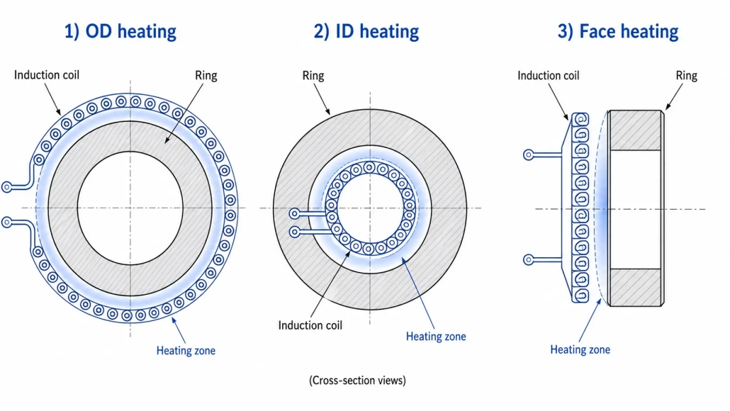
The coil determines where energy enters the part. For large rings, the heating objective dictates which surface the coil faces.
Coil positioned around the outside diameter. Most common — easy to load, straightforward rotation. Used for bearing rings, gear blanks, shrink fitting.
Coil placed inside the ring bore. Used when the inner surface needs heat — internal raceways, shrink-fit expansion from the ID, or when OD access is blocked.
Coil faces the ring’s flat surface axially. Suitable for flanges, broad face rings, or when heating must be distributed across the ring height rather than circumference.
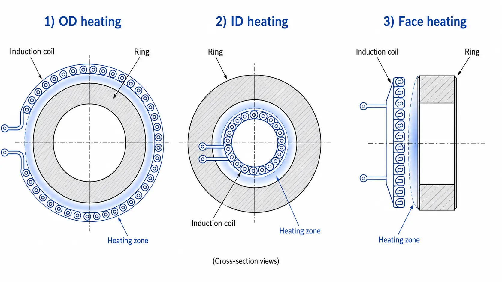
Single-turn coils suit large diameters where broad, even heating is the goal. Multi-turn coils improve coupling and concentrate heating but are physically harder to fit around large or irregular rings. Coupling gap should account for part runout, thermal expansion during heating, and loading clearance — typical gaps for large rings range from 3 to 15 mm depending on part condition and handling accuracy. More detail on coil design principles is covered in induction coil design.
5. Power Supply & Frequency
Power is sized from part mass, target temperature, cycle time, material, and estimated coil efficiency — not from ring diameter alone. A 2,000 mm ring with a 6 mm wall and a 2,000 mm ring with a 50 mm wall require substantially different power levels.
Frequency controls how deep current penetrates before heat is generated by conduction. For through-heating thick rings (wall > 20 mm), lower frequencies (1-10 kHz) drive current deeper. For surface hardening of raceways or tooth profiles, higher frequencies (10-100 kHz) concentrate heat at the surface. For thin-wall rings, medium frequencies (3-30 kHz) often provide a workable balance. These principles are explained further in induction heating fundamentals and power selection.
Higher power does not automatically produce a better result. Excessive surface power creates steep gradients, risking distortion or surface overheating before the mid-wall reaches temperature. A controlled ramp or staged power profile often produces more uniform results than running at full power for a shorter time.
6. Rotation & Temperature Control
Temperature uniformity around a large ring is the hardest part of the process to get right. Even a well-designed coil produces some circumferential variation — rotation averages this out. Rotation speed must be stable: too slow lets the zone facing the coil overheat; too fast makes temperature feedback harder to use.
Large rings rotate on rollers, turntables, or vertical spindles. The fixture must support the part safely at temperature and maintain consistent coil-to-part alignment throughout the cycle.
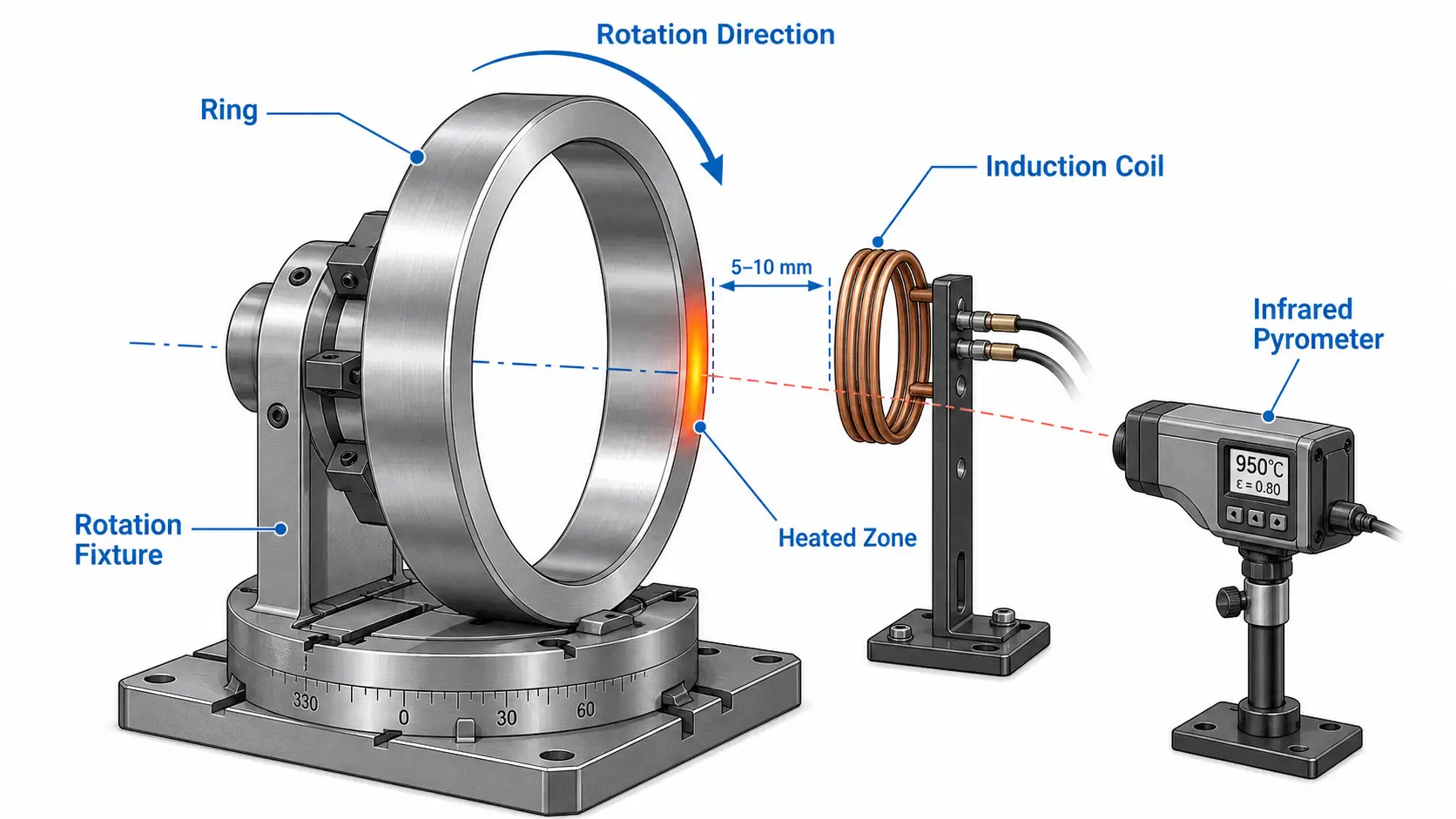
Infrared pyrometers are the standard for non-contact measurement, but emissivity variation from scale, surface finish, or steam affects readings. For process development, contact thermocouples or test coupons at multiple locations validate what the pyrometer sees. A single measurement point on the easiest-to-view surface rarely represents the hottest or coldest area of the ring.
Closed-loop control adjusts power based on measured temperature, useful when starting temperature or part mass varies between batches. A capable control system includes:
7. Common Problems & Solutions
Most problems trace back to a mismatch between the part, coil, power supply, or handling method. Testing with clear acceptance criteria catches these before they reach production.
Caused by poor coil alignment, inconsistent coupling, insufficient rotation, or geometry variation around the ring. Fixes: coil redesign, better fixturing, adjusted rotation speed, or longer soak. For hardening, uneven heating can produce soft spots or cracking — similar to issues covered in common hardening defects.
Thin-wall rings are sensitive to steep temperature gradients and inadequate support. Slower ramp rates, uniform rotation, and controlled cooling reduce distortion. Quench design matters as much as heating — an uneven quench can warp a perfectly heated ring.
Large ring coils carry high current and depend on reliable water cooling. Blocked passages, undersized tubing, or scale buildup damage coils and cause unplanned downtime. Flow and temperature monitoring on the water cooling system are essential.
Variation comes from different starting temperatures, inconsistent part mass, scale thickness, loading delays, or operator adjustments. Recipe control and documented setup procedures restore repeatability. For high-volume lines, temperature-based control reduces reliance on fixed timers.
8. What to Evaluate Before Buying
Start with the process, not the power supply. Define these before approaching suppliers:
Sample testing with the actual part often saves more time and cost than any amount of calculation. A test run confirms power requirements, heating time, temperature uniformity, coil geometry, and handling feasibility before the full system is built.
Key Takeaway
Induction heating for large rings works when the coil, power supply, rotation fixture, and temperature control are engineered around the specific part and process — not selected from a catalog by diameter. Coil coupling configuration (OD, ID, or face), frequency selection for the required heating depth, and closed-loop temperature control are the three factors that most determine success. For critical or high-value parts, sample testing with clear acceptance criteria is the most reliable way to reduce risk before purchase.
FAQ
💡 Click each question to expand the answer
What frequency is best for induction heating large rings?
Can induction heat a large ring evenly?
Is induction better than a furnace for large rings?
What information is needed for a system quotation?
Evaluate Your Large Ring Heating Process
Share your ring dimensions, material, target temperature, and production rate. Our engineering team can review the application and recommend a practical induction heating approach.


