
Why Is My Induction Heating Uneven? Causes, Diagnosis, and Practical Fixes
A hardening line starts turning out parts with soft spots on one side. A brazing station that ran fine last week suddenly won’t flow alloy evenly around the joint. An operator keeps nudging the pyrometer aim point because the temperature reading “looks wrong” compared to what the part is doing.
Uneven induction heating rarely announces itself with a clear error code. It shows up as pattern drift, rising scrap, and operators who’ve learned to work around a process they no longer trust.
The cause is almost never one thing. It’s usually two or three variables that drifted just enough, together, to push the process out of its window. This article walks through how to trace the symptoms back to the real cause — before you spend money on a coil you don’t need or a power supply that wasn’t the problem.
| 1. How to Spot It & What’s Behind It | 2. Coil Design & Part Position |
| 3. Frequency & Power Settings | 4. Material, Geometry & Surface |
| 5. Motion, Fixturing & Quench | 6. Troubleshooting Method |
1. How to Spot It and What’s Usually Behind It
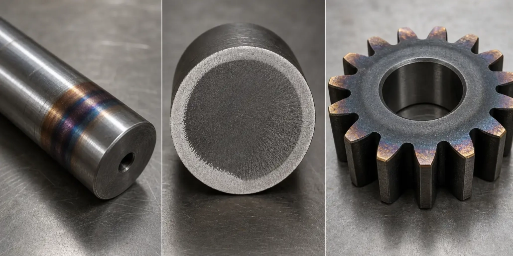
Uneven heating shows up differently depending on the process. In hardening: shallow case on one side of a shaft, soft spots near a shoulder, pattern length drifting part to part. In brazing: alloy flows on one side of the joint, or one component overheats while the mating part barely reaches temperature.
Operators notice before the QC report does. One side glows earlier. The temperature controller hunts. Someone starts nudging the pyrometer aim point every few cycles. In automated cells, it’s sneakier — a slow drift that piles up scrap for half a shift before anyone catches it.
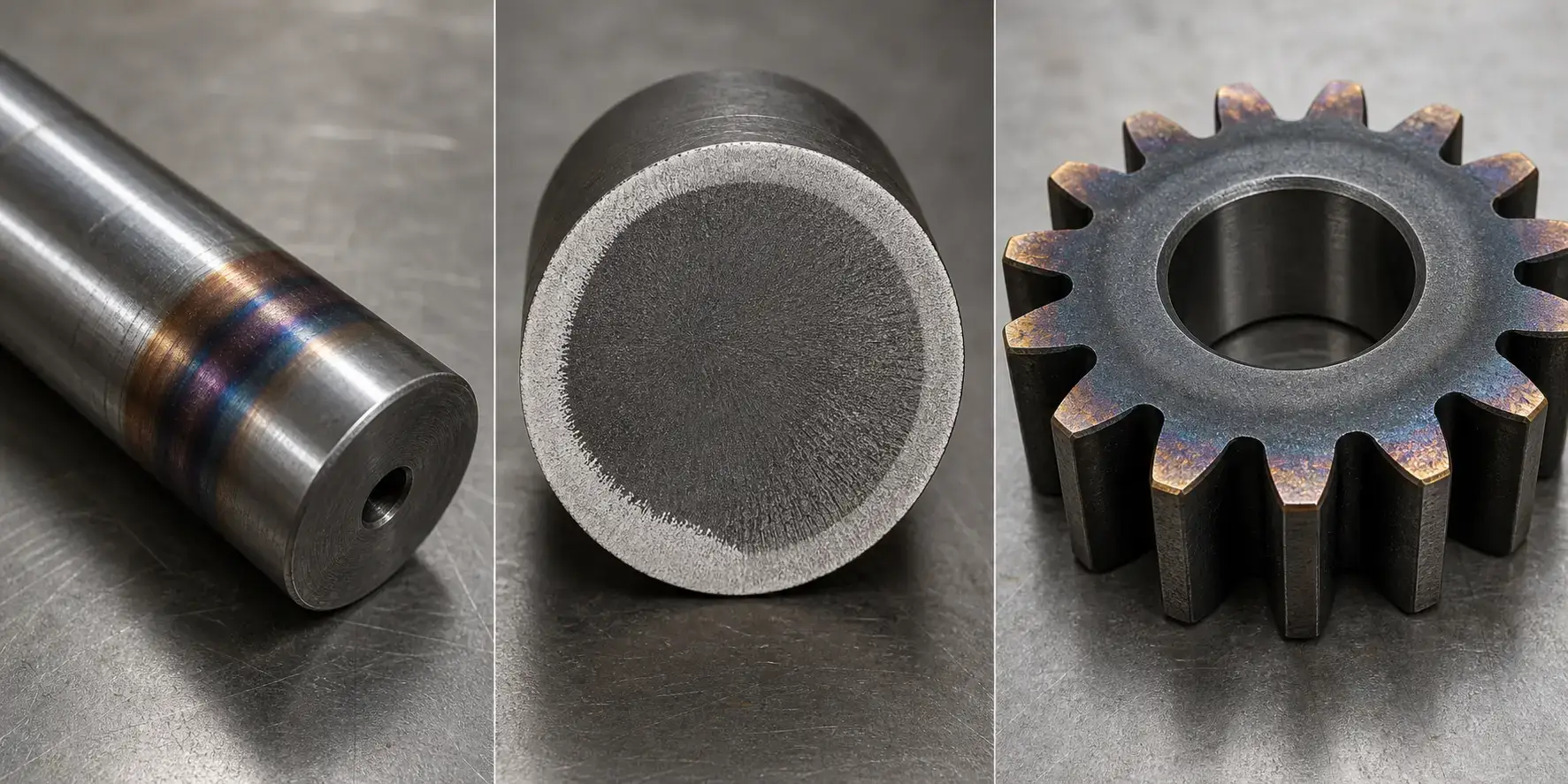
Before you start, pin down what “uneven” means for your application. A 15°C spread might scrap a hardening job but be invisible in a preheat step. The limit comes from the metallurgy and the downstream process — not from what the machine can hold on a good day.
Once you’ve defined the tolerance, the cause almost always falls into one of these buckets:
— Coil and part don’t fit each other — wrong shape, wrong turn spacing, return leg too close
— Part position wanders — off-center, tilted, or shifting mid-cycle
— Wrong frequency for the depth — too high cooks the surface; too low spreads heat everywhere
— Power is too aggressive for the geometry — short hot cycles make every non-uniformity worse
— Motion or fixturing drifted — worn rollers, scan axis sticking, locator thermal shift
— Material changed without telling you — new supplier, different chemistry, residual stress from upstream
— It’s the quench, not the heat — plugged spray holes, uneven flow, polymer concentration off
— Someone already “fixed” it once — floor-level recipe tweaks compensating for a mechanical problem, now baked in
Below, we go through them in the order you should check — free inspections first. For fundamentals, see how induction heating works.
2. Coil Design and Part Position: Start Here
Nine times out of ten, it’s the coil and the part not lining up. Not the power supply. Not the recipe. A geometry problem.
The gap between the coil and the part surface controls how efficiently energy transfers. The closer side heats faster. Even a millimeter off-center at tight gaps puts noticeably more flux into one side than the other. This is the most common cause of circumferential non-uniformity, period. The root cause is usually mechanical: a worn locator, a bent shaft sagging between centers, or fixture growth after the machine’s been running hot for hours.
Rotation averages out small variations but won’t save a bad coil match or a crooked load. If the part is spinning and you still see a pattern, it’s the coil shape or the loading repeatability.
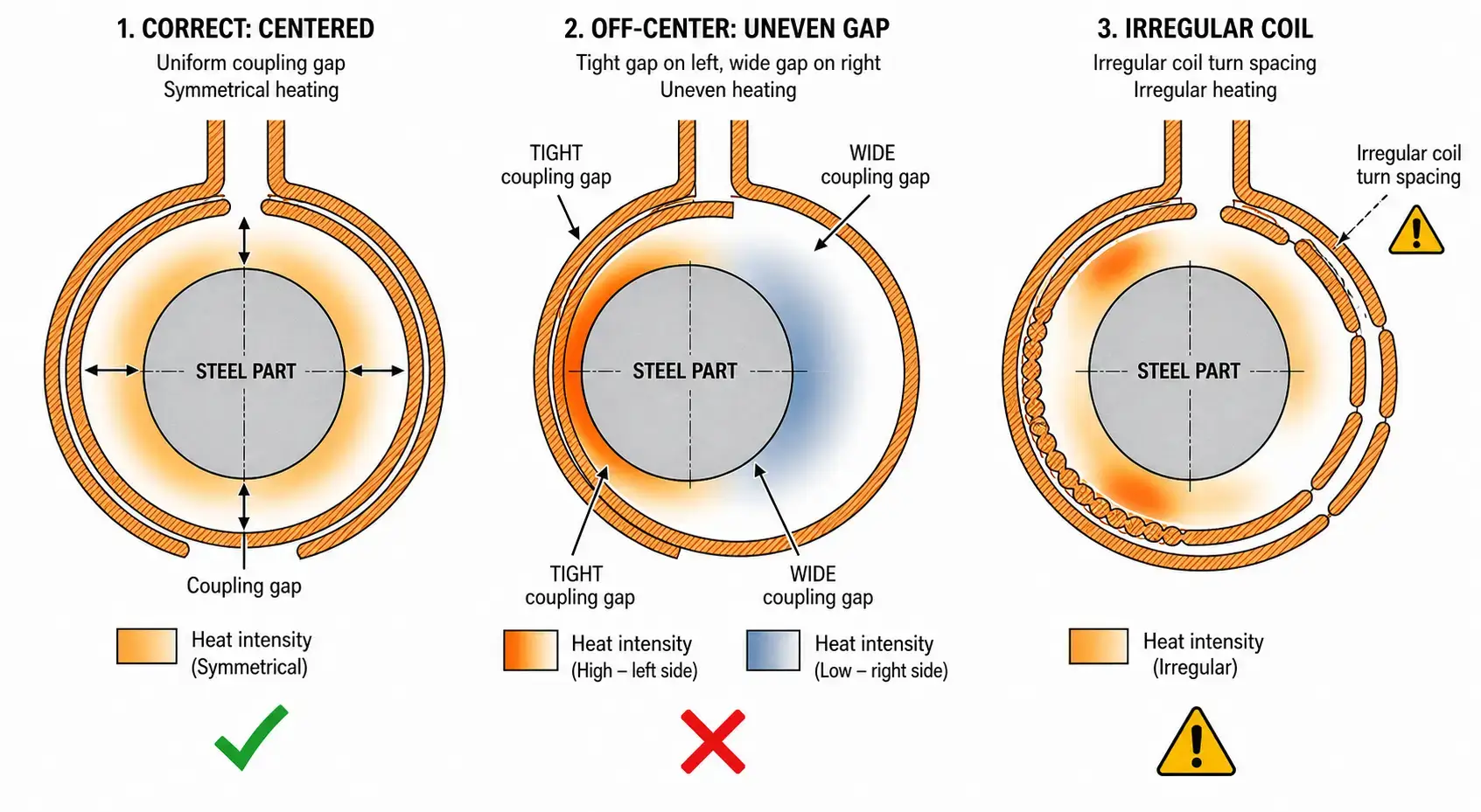
Coil shape matters as much as gap. Common trouble spots: uneven turn spacing, coil face not parallel to the part, a return leg sitting too close, or a coil that’s too long for a narrow heat band. Also check magnetic flux concentrators — one cracked or missing concentrator can shift the pattern enough to look like a power supply fault.
Quick test: swap in a known-good coil, same recipe. If the pattern changes, you’ve found your variable. See induction coil design for more.
3. Frequency and Power Settings
If the coil and position check out, look at frequency next. Frequency sets how deep the current penetrates. Too high and the surface cooks while the core stays cold. Too low and the heat spreads past your target zone.
| Symptom | Likely Frequency Issue | What to Try |
|---|---|---|
| Surface overheats while core stays cold | Frequency too high for the wall thickness | Lower the frequency or add soak time for thermal conduction |
| Heat spreads too far beyond the target zone | Frequency too low, heating too deep | Increase frequency for shallower penetration |
| Edges and corners glow before flat surfaces | High power density + high frequency amplifying edge effect | Reduce power, extend cycle time, or add flux concentrators to redirect field |
| Pattern drifts as the part heats | Frequency not accounting for Curie transition (~770°C) | Validate frequency choice in both magnetic and non-magnetic regimes |
Power and frequency interact. High power, short time: every non-uniformity gets amplified. Lower power, longer soak: conduction has time to even things out.
If someone recently “optimized” the cycle for speed without touching the coil or frequency, that’s your suspect. The pyrometer says the part hit setpoint. But it’s only reading one spot — and 40°C away, another zone hasn’t caught up.
See frequency selection and power selection for more.
4. Material, Geometry, and Surface Condition
Sometimes the machine is fine. The part changed.
Different alloys heat differently — carbon steel, stainless, and aluminum each respond in their own way. Even within the same grade, a new supplier with slightly different chemistry can shift the heating response enough to matter. Nobody checks the material cert for weeks because “it’s the same grade we’ve always used.”
Part geometry creates its own hotspots. Sharp corners heat faster than flats. Thin walls reach temperature before heavy sections. Holes, keyways, and splines disrupt the current path. These aren’t process defects — they’re features of the part that the coil needs to work around.
Surface condition throws off more than just the heating. Scale, decarb, plating, or coatings change both the electrical coupling and the emissivity your pyrometer reads. If the surface finish changed and nobody recalibrated, the control loop is chasing a temperature that isn’t real. See common induction hardening defects for examples.
5. Motion, Fixturing, and the Quench Illusion
A good recipe drifts when the mechanical side drifts. Nobody checks rotation speed, scan rate, or fixture position until the scrap pile is already tall.
Rotation problems are straightforward: if hot and cold bands line up with rotation speed, the drive rollers are slipping, worn, or pressing unevenly. A bent shaft or poor concentricity produces the same pattern.
Scan hardening: if the axis pauses or accelerates, you’ll see hardness bands that match the motion profile. Small speed changes equal real differences in heat input per unit length.
Fixture wear is the quiet one. Over months, a locator shifts the part position. Thermal expansion moves it further once the machine is hot. Measure cold, measure again after an hour. If the numbers differ, your process window has been closing all shift.
And the quench: a part can heat evenly and cool unevenly. Plugged spray holes, asymmetric flow, wrong polymer concentration, a misaligned ring — all of it looks like a heating defect. Before you tear into the coil, verify the quench. See water cooling systems for induction heating.
6. How to Troubleshoot Without Making It Worse
Changing three things at once turns a problem into a mystery. Isolate one variable per test.
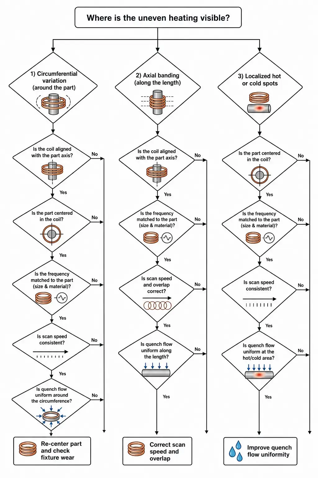
Start free. Inspect the coil. Verify part position cold and hot. Measure the coupling gap. Confirm the recipe on the screen matches the approved version — not what someone tweaked last month.
Then isolate: swap a known-good coil, try a different material batch, compare cold-start results to mid-shift. If the pattern follows one variable, that’s your trail.
Call the supplier when you’ve got evidence of power instability, impedance mismatch, or capacity limits — not before. Bring part drawings, material specs, cycle data, coil photos, and hardness results. The more you hand them, the less likely you walk away with hardware you don’t need.
Key Takeaway
Uneven induction heating is rarely one thing. It’s a gap, a position, a frequency, or a mechanical drift — usually misdiagnosed as electrical. Check the coil and part position first. One variable at a time. And don’t let the quench send you chasing a heating problem that isn’t there.
FAQ
Why does one side of my part heat faster?
Almost always because that side sits closer to the coil. Check part centering, coil symmetry, and whether the return leg is influencing one side of the field. Rotation helps average it out but doesn’t fix the root misalignment.
Can the wrong frequency cause uneven heating?
Yes. Too high and the surface cooks before heat conducts inward, especially near edges and corners. Too low and you can’t localize the heat, so adjacent areas come up to temperature when they shouldn’t. Frequency needs to match the part geometry and the required heating depth together.
How do I know if it’s the coil or the power supply?
Swap in a known-good coil and run the same recipe. If the pattern changes, it’s coil or tooling. If output power or frequency is unstable across multiple coils and parts, the supply or the load matching needs attention. But most “power supply problems” turn out to be tooling problems that the power supply is being asked to compensate for.
Send us your part details, heat pattern requirements, and current equipment information. Our engineering team can help identify likely causes of uneven heating and recommend practical next steps.


