
Hartowanie indukcyjne łożyska stożkowego z rowkiem kątowym: Wybór induktora & Poradnik zasilania
Angular groove hub bearing induction hardening presents a unique challenge: the bearing’s sloped (angular) groove surfaces are asymmetric, making uniform heating far more difficult than on a flat or cylindrical surface. Get the inductor design wrong, and you’ll see uneven case depth — too shallow at the groove center, too deep on one side. Zrób to poprawnie, and you’ll hold a tight hardness window across both grooves with minimal parameter tweaking. This guide compares the two inductor configurations that dominate production and helps you pick the right one for your line.
Spis treści
1. Dlaczego rowki kątowe są trudniejsze do wzmocnienia
Zwykłe pierścienie łożysk mają płaskie lub proste cylindryczne bieżnie. Nagrzewanie indukcyjne jest proste: cewka owija się wokół lub znajduje się wewnątrz części, a pole magnetyczne rozkłada się równomiernie na powierzchni docelowej.
Łożyska z koszykiem o rowkach kątowych są inne. Powierzchnie rowków są nachylone pod kątem względem osi łożyska, and the upper and lower grooves are asymmetric — they sit at different axial positions and face different directions. This means:
- A standard cylindrical inductor cannot heat both grooves evenly
- The magnetic field coupling distance varies across the sloped surface, causing nierównomierny rozkład ciepła
- The second groove is always harder to heat consistently because the inductor’s position must be readjusted
These challenges exist regardless of bearing size — but they become more pronounced as the angular surface gets larger. Bearing manufacturers use materials like GCr15 (100Cr6) stal łożyskowa, with case depth typically specified at 1.5–3.5 mm and hardness at 58–62 HRC. Dla bearing steel grades and hardening requirements are well standardized; the challenge is entirely about delivering heat where it’s needed.
2. Podejście 1: Single-Turn Profiled Inductor — Two Steps, Wysoka sprawność
Jak to działa
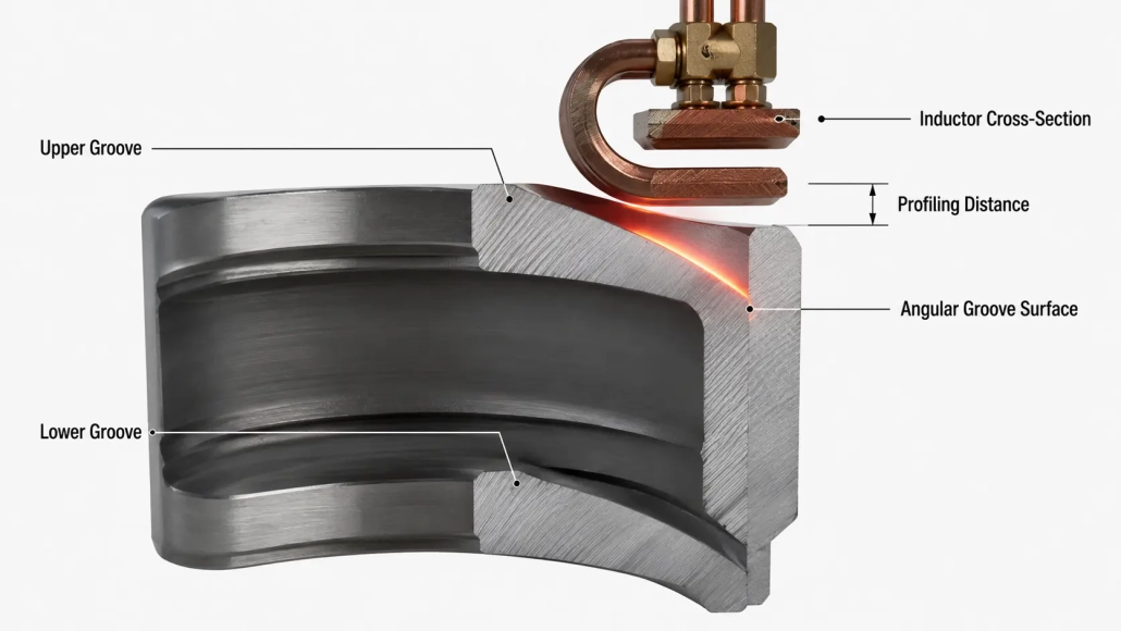
A single-turn copper inductor is machined with a kontur, który ściśle pasuje (profile) kątowa powierzchnia jednej rowka. Pierwszy rowek jest utwardzany, następnie induktor jest przestawiany — regulacja wysokości i parametrów grzania — i przetwarzany jest drugi rowek. Pomyśl o tym jak o narzędziu precyzyjnym, które obejmuje obrabiany element: bliskie dopasowanie, wysoki transfer energii.
Co sprawia, że działa dobrze
Wydajność grzania jest wyróżniającą się zaletą. Ponieważ profil induktora ściśle podąża za geometrią rowka, odległość sprzężenia pola magnetycznego jest minimalizowana — co oznacza, że więcej energii trafia do obrabianego materiału, a mniej jest tracone. dla dobór źródła zasilania do nagrzewania indukcyjnego, to przekłada się na niższe zapotrzebowanie mocy dla tej samej głębokości obróbki cieplnej, lub głębsze utwardzanie przy tym samym poziomie mocy.
Gdzie może dojść do problemów
Głównym punktem krytycznym jest drugi rowek. Ponieważ górne i dolne rowki są umieszczone asymetrycznie, wysokość induktora i parametry nagrzewania muszą być każdorazowo dostosowywane. Dla łożysk z dużymi powierzchniami kątowymi, two specific defects can appear:
- Shallow center: insufficient case depth at the midpoint of the groove, where the magnetic field coupling is weakest
- One-sided depth: excessive case depth on one side of the groove, caused by uneven profiling distance
The fixes: adjust the profiling distance between inductor and workpiece in the opposite direction (reverse profiling) to compensate for thermal asymmetry. If that doesn’t resolve it, switch from a single-turn to a two-turn (double-loop) induktor — the second turn redistributes current flow, evening out the heating pattern. This is similar in principle to techniques discussed in our guide to wyzwania związane z hartowaniem indukcyjnym wałów, where inductor profiling distance is also the primary lever for case depth control.
3. Podejście 2: U-Shaped Inductor — Single Shot, Both Grooves at Once
Jak to działa
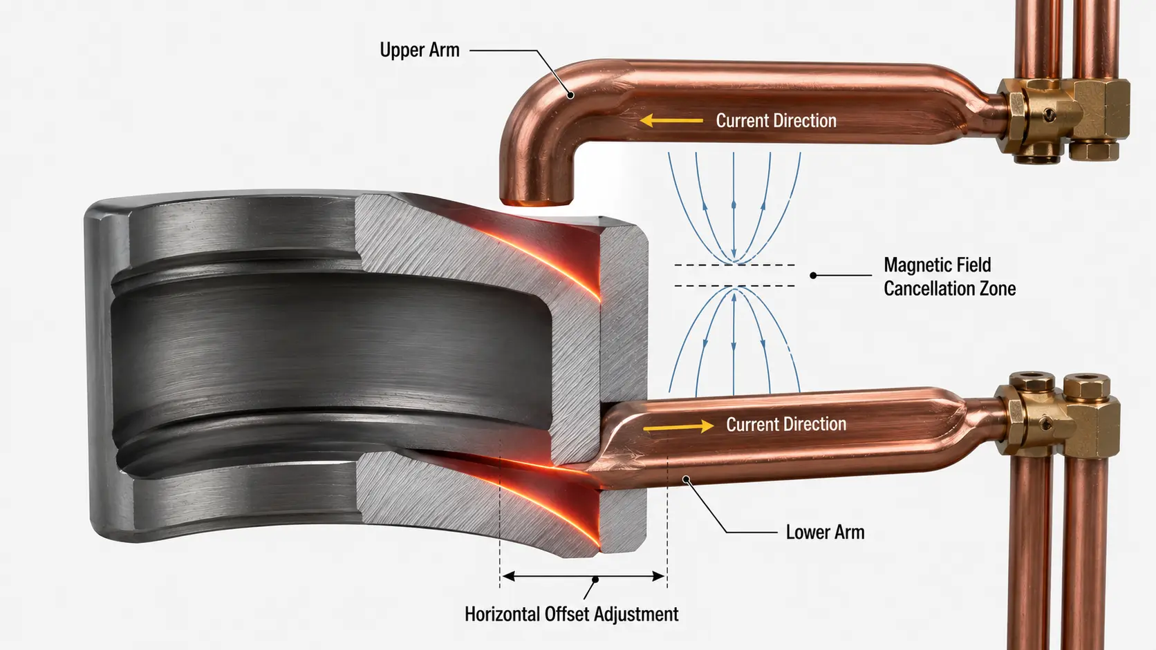
The inductor is shaped as a horizontal U-shaped half-loop. In one heating cycle, both angular grooves are hardened simultaneously. The hardening machine must have horizontal offset (translation) capability aby precyzyjnie wyrównać induktor z obiema powierzchniami rowka.
Kompromis wydajności
Konstrukcja w kształcie litery U ma wbudowane fizyczne ograniczenie: to prąd w górnym i dolnym ramieniu płynie w przeciwnych kierunkach. Oznacza to, że ich pola magnetyczne częściowo się znoszą, reducing the net heating effect on the workpiece. The result is lower heating efficiency compared to the single-turn profiled approach.
W rzeczywistości, this means you’ll need a higher-power power supply to achieve the same case depth, or accept a slightly longer heating cycle. Odniesienie do induction heating frequency classifications to ensure your power supply — typically super-audio frequency (10–40 kHz) for bearing applications — can deliver sufficient power density for the U-shaped configuration.
The Precision Risk
Horizontal offset is the critical parameter here. If the translation is set incorrectly, the inductor can make physical contact (collision) with the workpiece — causing immediate damage to both the inductor and the bearing. Even without collision, a misaligned offset produces uneven heating between the two grooves, defeating the purpose of single-shot hardening. This is not a set-it-and-forget-it setup: the offset must be verified and adjusted for each bearing model.
4. Porównanie obok siebie
| Czynnik | Single-Turn Profiled (Dwustopniowy) | w kształcie litery U (Jedno uderzenie) |
|---|---|---|
| Heating Efficiency | Wysoki — kontur dokładnie podąża za rowkiem | Niższy — przeciwne prądy częściowo się znoszą |
| Czas cyklu | Dłuższy — dwa oddzielne cykle nagrzewania | Krótszy — oba rowki w jednym cyklu |
| Jednorodność głębokości hartowania | Dobra, ale drugi rowek może wymagać korekty profilu | Dobre przy prawidłowym ustawieniu przesunięcia; nierównomierne przy błędnym ustawieniu |
| Wymagania maszyny | Standardowa maszyna do hartowania; tylko regulacja wysokości | Musi mieć poziome przesunięcie (translation) capability |
| Złożoność ustawienia | Niższa — jeden rowek na raz, prostsze ustawienie | Wyższa — przesunięcie musi być precyzyjnie skalibrowane dla każdego modelu |
| Ryzyko kolizji | Low — inductor positioned clear of opposing groove | Moderate — misaligned offset can cause contact |
| Best for Batch Size | Low to medium volume; mixed SKU production | High volume; dedicated long-run production |
5. Jak wybrać dla swojej linii produkcyjnej
Pick the Single-Turn Profiled Approach If:
- Your production runs are low to medium volume (hundreds, not thousands per day)
- You process multiple bearing SKUs on the same machine and need quick changeover
- Your hardening machine does not have horizontal offset capability
- You prioritize heating efficiency and energy cost over raw cycle speed
- You’re willing to accept a secondary profiling adjustment for the second groove
Pick the U-Shaped Approach If:
- Your line runs high volume with tight cycle-time targets
- You’re producing a single bearing model in long dedicated runs
- Your hardening machine has horizontal offset functionality (or you’re budgeting for one)
- You have skilled setup technicians who can calibrate the offset precisely per model
- You’re willing to oversize the power supply to compensate for lower heating efficiency
Uwagi na temat wymiarowania zasilacza
Bez względu na wybraną metodę, wybór mocy nagrzewania indukcyjnego łożyska wzdłużne powinny uwzględniać naturalną stratę wydajności wynikającą z ukośnej geometria. Dobre praktyczne zasady: dobierz zasilacz 15–25% wyższy niż sugerowałoby to obliczenie utwardzania powierzchni płaskiej dla tej samej głębokości obróbki. Ten zapas zapewnia stałe nagrzewanie nawet przy wyzwaniach profilowania i sprzężenia opisanych powyżej.
Dla dalszej lektury, to Podręcznik ASM dotyczący nagrzewania indukcyjnego i obróbki cieplnej provides extensive reference data on inductor design principles and case depth prediction across a range of geometries. For flux concentrator selection — particularly relevant if you’re adding concentrators to a U-shaped inductor to boost efficiency — Fluxtrol offers detailed technical resources on magnetic flux concentrator materials.
🔑 Kluczowa Konkluzja
The single-turn profiled inductor is the safer default for most shops: higher efficiency, simpler machine requirements, and easier setup. Its main cost is a second heating cycle and a possible profiling tweak for groove two.
The U-shaped inductor is the cycle-time play: both grooves in one shot, but you’ll pay for it with lower efficiency, a more capable machine, and tighter setup discipline. It earns its place in high-volume dedicated lines — not in a mixed-SKU job shop.
Need Help Sizing an Inductor for Angular Groove Bearings?
Our engineering team can review your bearing geometry, wolumen produkcji, i specyfikacje maszyny, aby zalecić odpowiednią konfigurację induktora i zasilanie. Szybka ocena techniczna, Bez zobowiązań.


