
Induction Brazing Coil Design: How to Match Coil Geometry to Joint Type and Production Requirements
How Joint Geometry, Filler Metal Placement, and Production Access Shape Induction Brazing Coil Design
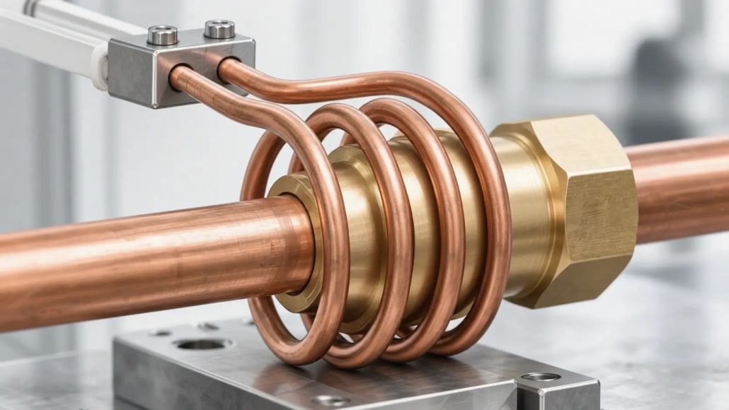
Induction brazing coil design is not simply a matter of choosing a coil shape that fits around a workpiece. The coil must be positioned and configured according to the joint geometry, filler metal location, material properties, and heating requirements.
A coil designed for a tube-to-fitting socket joint may not be suitable for a tube-to-plate T-joint. The two applications differ in their joining interfaces, component thicknesses, heating access, and workpiece positioning requirements.
These differences affect several aspects of coil design, including coil diameter, active heating length, turn spacing, coil-to-workpiece clearance, and whether an encircling, open, or split configuration is more appropriate.
Production requirements introduce another consideration. The coil must work with the actual loading method, fixture arrangement, and processing sequence.
This guide explains how to match induction brazing coil geometry to different joint configurations and how to evaluate the design for practical production applications.
2. Key Factors in Custom Induction Brazing Coil Design
3. Joint Clearance and Filler Metal Placement in Coil Design
4. Adapting Coil Design to Production Requirements
5. Coil Testing and Process Validation
6. What Information Is Needed for a Custom Induction Brazing Coil?
1. How Joint Geometry Determines Induction Brazing Coil Design
Before selecting an induction coil configuration, it is important to understand the geometry of the brazed joint.
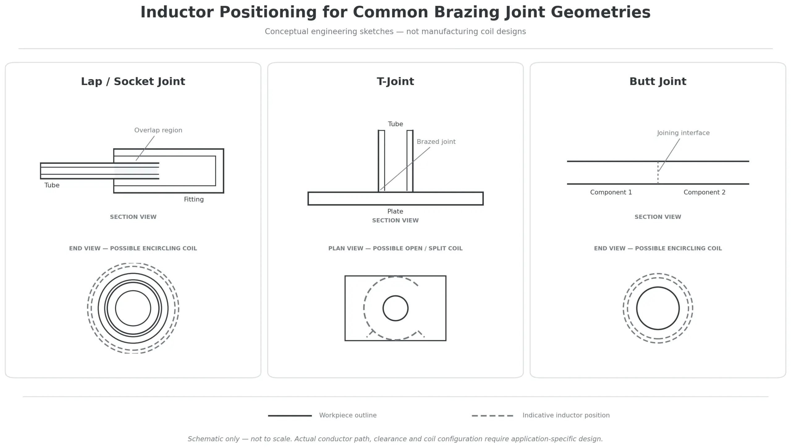
For coil design purposes, common joint configurations can be grouped into three main categories:
•Lap and overlap joints, including tube-to-fitting socket joints and sleeve connections.
•T-joints and corner joints, where components meet at an angle.
•Butt joints, where components meet at their ends.
These configurations are not interchangeable. Each creates a different joining area and may require a different approach to coil positioning and heating.
1.1 Coil Design for Lap and Overlap Joints
Lap joints are widely used in induction brazing. One component overlaps another, creating an interface where the brazing filler metal can flow and form the connection.
Tube-to-fitting socket joints and sleeve connections are common examples.
Tube-to-fitting socket joints
In a socket joint, one tube is inserted into a fitting or socket. The overlapping section forms the brazing interface.
An encircling coil is one possible configuration because it can surround the cylindrical joining area.
The design should consider:
•The outside diameter of the fitting
•The tube insertion depth
•The length of the overlapping section
•The wall thickness of both components
•The location of the brazing filler metal
•The available clearance around the assembly
The coil’s active heating region should be positioned in relation to the actual joining interface.
For example, when a relatively thin copper tube is connected to a thicker brass fitting, the two components may heat at different rates. Their different thermal masses, electrical properties, and heat conduction characteristics can influence the temperature distribution.
The coil position and heating cycle should therefore be evaluated together to achieve suitable conditions at the joining interface.
Sleeve and overlap connections
A sleeve joint typically connects two tube ends through an external sleeve that overlaps both components.
Although this is also an overlap joint, its geometry may create different heating requirements from a simple tube-to-fitting connection.
Important considerations include:
•The total sleeve length
•The position of both tube ends
•The location of the internal joining interfaces
•The distance between the joining areas
•The thickness and material of the sleeve and tubes
•Whether the assembly can be inserted into a closed coil
For a relatively short sleeve, one coil position may be sufficient to heat the required joining region.
For longer sleeves or assemblies with multiple joining interfaces, the coil’s active length and the heating sequence may need to be evaluated.
A longer coil does not automatically provide better heating. The resulting temperature distribution must be verified for the actual assembly.
1.2 Coil Design for T-Joints and Corner Joints
T-joints and corner joints have a different geometry from cylindrical lap joints.
A typical tube-to-plate T-joint consists of a tube positioned against a plate, with the joining interface located around the tube-to-plate connection.
These applications can be more difficult because the workpiece is not symmetrical around the joint.
The design may need to account for:
•Different component thicknesses
•Unequal thermal mass
•Different material properties
•Restricted coil access
•Nearby components that should not receive excessive heat
•The direction from which the workpiece enters the heating position
Why coil positioning becomes more challenging
When a tube is joined to a thicker plate, the two components may not reach the required brazing conditions at the same rate.
The coil must therefore be positioned according to the intended heating area rather than simply centered around the visible joint.
A suitable arrangement needs to consider the thermal response of both components and the heat transferred into surrounding areas.
Open and split coil configurations
For some T-joint applications, a conventional closed coil may be difficult to install around the assembly.
An open or split inductor can provide access for workpiece loading and may also allow the coil to accommodate more complex assembly geometries.
However, a split coil is not automatically the best solution for every T-joint.
Its design must still provide suitable electromagnetic coupling and heating coverage around the intended joining region.
A 2023 research study, Key Parameters and Optimal Design of a Split Induction Coil for T-Shaped Pipe Brazing, investigated a split coil for brazing multiple T-shaped aluminum pipe connections in a heat exchanger.
The researchers evaluated coil parameters and their effects on the electromagnetic field and temperature distribution. The optimized arrangement was used to braze three T-shaped joints simultaneously.
This study demonstrates how joint geometry, coil configuration, and production requirements can be considered together when developing a specialized induction brazing solution.
The reported dimensions and operating parameters belong to that particular research application and should not be treated as universal coil design values.
1.3 Coil Design for Butt Joints
In a butt joint, two components meet at their ends rather than forming an extended overlapping section.
For induction brazing, the joint design must provide appropriate conditions for filler metal placement and flow between the mating surfaces.
The coil is generally positioned in relation to the joining interface so that both components receive suitable heating.
Important design considerations include:
•The alignment of the two components
•The joint clearance
•The location of the filler metal
•The material and thickness of each component
•The accessible space around the joint
•The fixture required to maintain alignment during heating
One challenge is ensuring that the two mating components reach suitable brazing conditions at the same time.
This can be particularly important when joining dissimilar materials or components with significantly different thicknesses.
If one side of the joint becomes much hotter than the other, filler metal flow and wetting may be affected.
The coil geometry and position should therefore be evaluated together with the material combination and joint configuration.
2. Key Factors in Custom Induction Brazing Coil Design
Once the joint configuration is understood, the next step is to determine how the coil should be positioned and shaped.
Several design variables influence the resulting heating pattern. They should not be considered independently because changing one parameter can affect the electromagnetic and thermal behavior of the entire system.
2.1 Coil Position, Diameter, and Active Heating Length
Coil position
The coil should be positioned in relation to the actual brazing interface.
For a cylindrical socket joint, this may involve locating the coil around the fitting and overlapping section.
For a T-joint, the coil may need to approach the connection from a different direction to accommodate the tube and plate arrangement.
The objective is to deliver suitable heating to the joining region without unnecessarily concentrating heat in surrounding areas.
Coil diameter
For an encircling coil, the internal diameter determines the available space between the coil and the workpiece.
The diameter must accommodate the workpiece dimensions and the required coil-to-workpiece clearance.
An excessively large gap may reduce electromagnetic coupling, while insufficient clearance can create mechanical interference or prevent reliable loading.
The appropriate diameter depends on the workpiece geometry, operating conditions, and production tolerances.
Active heating length
The active heating length refers to the portion of the coil that contributes to heating the intended region.
For a short socket joint, the active region may be relatively localized.
For a longer sleeve connection, a longer heating region or a different heating sequence may be required.
The coil should be designed around the required heating coverage rather than simply matching the overall workpiece length.
2.2 Number of Turns and Turn Spacing
The number of turns and the spacing between turns influence the electrical characteristics of the inductor and the distribution of the electromagnetic field.
These factors need to be considered in relation to:
•The workpiece dimensions
•The intended heating region
•The material properties
•The operating frequency
•The available power supply
•The required heating cycle
A multi-turn coil may be suitable for applications requiring heating over a longer region.
A single-turn or specially shaped coil may be more appropriate for localized heating.
However, increasing the number of turns does not automatically improve heating performance.
Turn count, coil dimensions, electrical impedance, and power supply compatibility must be evaluated together.
Turn spacing also matters.
For cylindrical workpieces, the spacing between adjacent turns can influence the heating pattern along the axis of the component.
For complex joints, the spacing may need to be adjusted to account for the position of the joining interface and nearby features.
The appropriate arrangement should be determined through engineering evaluation and application testing.
2.3 Open, Split, and Encircling Coil Configurations
The physical configuration of the coil determines how it can be positioned around the workpiece and how easily the assembly can be loaded and removed.
Encircling coils
An encircling coil surrounds the workpiece and is commonly considered for cylindrical components and circumferential joining areas.
Potential applications include:
•Tube-to-fitting socket joints
•Sleeve connections
•Other cylindrical brazing assemblies
Its suitability depends on the workpiece dimensions, required heating coverage, and loading arrangement.
Open coils
An open coil provides access to the workpiece from an open side.
This may be useful when the assembly cannot conveniently pass through a closed coil or when surrounding components restrict installation.
The opening must be considered during electromagnetic and thermal design because it can influence the resulting heating pattern.
Split coils
A split coil is designed in separate sections or with an opening that allows it to accommodate the workpiece or production arrangement.
Split configurations may be considered for:
•Complex workpiece geometries
•Restricted loading access
•Assemblies with multiple joining locations
•Applications involving automated movement or positioning
A split coil can provide useful access, but its electromagnetic performance must be evaluated for the specific arrangement.
The selection between encircling, open, and split configurations should be based on the joint geometry, heating requirements, and production access.
3. Joint Clearance and Filler Metal Placement in Coil Design
Coil design cannot be separated from joint preparation.
Even when the coil provides suitable heating, an incorrect joint clearance or unsuitable filler metal placement can prevent satisfactory brazing.
3.1 Why Joint Clearance Matters
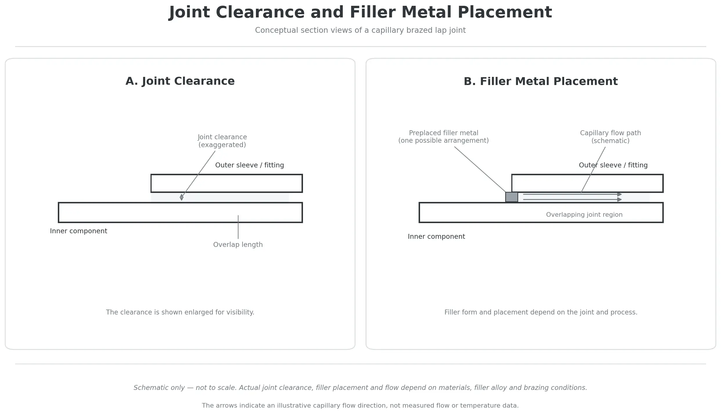
Joint clearance is the space between the mating surfaces of the components being joined.
In many brazing applications, molten filler metal enters this space through capillary action.
The appropriate clearance depends on:
•The base materials
•The selected filler metal
•The brazing process
•The joint geometry
•The temperature conditions during brazing
If the clearance is unsuitable, filler metal may not flow or fill the intended joining region correctly.
It is important to understand that the clearance at brazing temperature may differ from the clearance measured at room temperature.
Different materials expand by different amounts during heating.
For example, when joining a copper tube to a steel fitting, the two components may experience different thermal expansion. The resulting joint clearance can change during the heating cycle.
The coil design must therefore be considered together with the actual joint dimensions and material combination.
An induction coil cannot compensate for an incorrectly designed or poorly prepared joint.
For more information about the relationship between joint clearance, wetting, and brazing filler metals, see our related article on Induction Soldering vs. Induction Brazing.
3.2 How Filler Metal Placement Influences Coil Position
Brazing filler metal can be supplied in different forms, including:
•Preformed filler metal rings
•Brazing wire
•Brazing paste
•Other application-specific preforms
Its location affects where the heating process needs to establish suitable conditions.
For example, a filler metal ring positioned near the opening of a socket joint may require a different heating arrangement from filler metal placed directly at an internal joining interface.
The coil should be designed to heat the mating components appropriately so that the filler metal can melt, wet the surfaces, and flow into the joint.
In many induction brazing arrangements, the workpieces are heated by induced currents and the filler metal receives heat through conduction from the surrounding components.
The exact heating behavior depends on the materials, filler metal properties, dimensions, and position.
The important design principle is to consider the coil, filler metal, and joint as one system.
The coil should not be designed without knowing where the filler metal will be placed and how it is expected to enter the joint.
3.3 Heating Distribution Around the Brazing Interface
The objective of induction brazing is not simply to produce the highest possible temperature at one location.
The mating surfaces must reach suitable brazing conditions so that the filler metal can wet and fill the intended joint.
Depending on the application, the desired temperature distribution may need to be relatively uniform around the joint.
In other applications, a carefully controlled temperature difference may be considered to influence filler metal flow.
The appropriate thermal profile depends on the joint design, materials, filler metal, and brazing procedure.
For dissimilar materials, this evaluation becomes particularly important because their electromagnetic and thermal properties may differ.
A suitable coil design must therefore be verified under actual application conditions rather than judged by its physical appearance alone.
4. Adapting Coil Design to Production Requirements
A coil that works well for an individual laboratory sample may not be suitable for a production line.
The design must also accommodate workpiece handling, fixture arrangements, cycle time, and the required level of processing consistency.
4.1 Workpiece Loading and Unloading
The workpiece must be positioned correctly relative to the coil before heating begins.
The loading method influences whether an encircling, open, or split configuration is practical.
For example:
•A simple tube assembly may be inserted axially into an encircling coil.
•A large assembly may require an open or split arrangement.
•A complex component may need a specially designed fixture to reach the heating position.
The finished brazed assembly must also be removable after processing.
The coil should therefore be designed with both initial loading and post-brazing removal in mind.
4.2 Positioning and Fixturing
A fixture helps maintain the relative position of the components during brazing.
This is important because movement during heating can change the joint clearance and affect the final connection.
The fixture should consider:
•Component alignment
•Joint clearance
•Workpiece stability
•Thermal expansion
•Access for the induction coil
•Ease of loading and removal
For production applications, consistent positioning is particularly important.
If the joint moves relative to the coil from one cycle to another, the resulting heating conditions may also change.
The coil and fixture should therefore be developed as compatible parts of the same production arrangement.
4.3 Single-Joint and Multiple-Joint Processing
Some workpieces contain only one brazing joint, while others have several joining locations.
For a single-joint application, the coil can be designed around one defined heating area.
For multiple-joint assemblies, there are several possible approaches:
•Heating one joint at a time
•Moving the coil between joining locations
•Using multiple coils or processing stations
•Designing a specialized coil arrangement to heat several joints in one cycle
Simultaneous heating can reduce processing time, but it introduces additional design requirements.
The heating conditions must be suitable at all intended joining locations.
Differences in joint geometry, material thickness, and electromagnetic coupling can make this challenging.
A multi-joint coil should therefore be evaluated for the complete assembly rather than designed by simply extending a single-joint coil.
The previously mentioned T-shaped pipe brazing research provides an example of how a split coil can be developed for simultaneous processing of multiple joints.
4.4 Coil Compatibility with the Induction Heating System
The coil must also be electrically compatible with the induction heating power supply.
Its geometry and electrical characteristics influence the load presented to the generator.
Important considerations include:
•Available output power
•Coil inductance
•Current requirements
•Electrical connections
•Cooling requirements
A coil that is mechanically suitable for the workpiece may still require electrical adjustment to operate correctly with the selected power supply.
For this reason, coil design and equipment selection should be considered together.
For a broader explanation of coil configurations and basic design principles, see our guide: How Induction Coils Work.
5. Coil Testing and Process Validation
A proposed coil configuration should be evaluated under representative brazing conditions before it is finalized for production.
The purpose of testing is to confirm that the intended joining area receives suitable heating and that the finished joint meets the application’s requirements.
Several aspects should be evaluated.
Heating behavior
Check whether the joining interface reaches the required brazing conditions within the intended heating cycle.
Temperature measurements should be selected and positioned according to the workpiece geometry. An accessible external surface measurement may not represent the temperature inside a concealed joint.
Filler metal flow
Observe whether the filler metal melts, wets the mating surfaces, and fills the intended joining area.
For capillary joints, external appearance alone may not confirm complete internal filling.
Surrounding component temperatures
Check whether nearby areas receive excessive heat.
This is particularly important for thin sections, dissimilar materials, and assemblies containing temperature-sensitive components.
Finished joint quality
Depending on the application, inspection may include:
•Visual examination
•Cross-sectional examination
•Leak testing
•Mechanical testing
•Electrical testing
•Other application-specific quality checks
The appropriate inspection method depends on the function and acceptance requirements of the finished assembly.
Production repeatability
Once a suitable process has been established, representative production trials should confirm that the heating and joint quality remain consistent.
Workpiece positioning, filler metal placement, coil alignment, and heating conditions should be controlled throughout production.
A successful single brazing cycle is not sufficient evidence of a stable production process.
6. What Information Is Needed for a Custom Induction Brazing Coil?
Before designing a custom induction brazing coil, it is important to understand the complete workpiece and production requirements.
The following information helps establish a suitable starting point.
| Required information | Design purpose |
|---|---|
| Workpiece drawing or physical sample | Understand the actual component geometry |
| Base material specifications | Evaluate material properties and heating behavior |
| Component dimensions | Determine coil size and positioning |
| Wall thickness | Evaluate differences in thermal response |
| Joint type and dimensions | Identify the joining interface and heating region |
| Joint clearance | Understand the required filler metal flow conditions |
| Filler metal specification | Establish the required brazing conditions |
| Filler metal form and position | Determine how the filler enters the joint |
| Target brazing temperature | Define the process thermal requirements |
| Heating cycle requirements | Establish the intended processing time |
| Induction power supply information | Evaluate electrical compatibility |
| Loading and unloading method | Determine coil accessibility |
| Production quantity and cycle time | Evaluate the production arrangement |
| Fixture and positioning requirements | Establish workpiece repeatability |
| Joint quality requirements | Define the required inspection and validation |
A two-dimensional drawing, three-dimensional model, or physical workpiece sample can help clarify the geometry.
Photographs of the actual assembly and its intended brazing position are also useful.
For more complex applications, preliminary testing may be necessary to evaluate the coil configuration and heating behavior.
The final design should be based on the actual workpiece rather than a generic coil shape.
Frequently Asked Questions About Induction Brazing Coil Design
Click a question to expand the answer.
What is the best coil for induction brazing?
There is no single best coil configuration for every application. Encircling coils may be suitable for cylindrical socket and sleeve joints, while open or split configurations may be considered for complex geometries or restricted loading access. The selection depends on joint geometry, material properties, heating requirements, and production conditions.
Can one induction brazing coil be used for different joint sizes?
It may be possible when the workpiece dimensions and heating requirements are sufficiently compatible. However, changes in diameter, wall thickness, joint length, or coil clearance can influence heating behavior. Different workpiece sizes may require interchangeable coils or application-specific arrangements.
Why is a split induction coil used for brazing?
A split coil can provide access to workpieces that cannot easily be inserted into a conventional closed coil. It may also be useful for specialized assemblies containing multiple joining locations. However, its electromagnetic performance and heating distribution must be evaluated for the specific application.
Does the coil need to heat the brazing filler metal directly?
Not necessarily. In many conventional induction brazing applications, induced currents primarily heat the base materials around the joint. Heat is then transferred to the filler metal through conduction. The actual heating behavior depends on the electrical and thermal properties of the materials and the filler metal arrangement.
How does joint clearance affect induction brazing coil design?
Joint clearance determines the space available for molten filler metal to enter and fill the joining interface through capillary action. The coil must provide suitable heating conditions for the selected filler and joint design. The clearance at brazing temperature should also be considered because thermal expansion can change the dimensions of the assembly.
Can multiple brazing joints be heated simultaneously?
Yes, in some applications. A specialized coil can be developed to heat multiple joining locations during one cycle. However, each joint must receive suitable heating conditions. Differences in geometry, material thickness, and electromagnetic coupling need to be considered and validated.
What is the difference between general induction coil design and induction brazing coil design?
General induction coil design explains the basic principles of coil geometry, electrical characteristics, coupling, and cooling. Induction brazing coil design applies these principles to a joining application. It places additional emphasis on joint geometry, filler metal placement, joint clearance, heating distribution, and workpiece positioning.
Conclusion
Induction brazing coil design should begin with the joint geometry and the requirements of the finished assembly.
Lap joints, socket connections, T-joints, corner joints, and butt joints create different heating and access conditions. These differences influence coil position, diameter, active heating length, turn arrangement, and the choice between encircling, open, and split configurations.
The design must also consider joint clearance, filler metal placement, material properties, and thermal expansion.
For production applications, loading, fixturing, electrical compatibility, and process repeatability are equally important.
A suitable induction brazing coil is therefore not simply a coil that fits around a workpiece. It is an application-specific inductor developed to match the joint structure, heating requirements, and intended production process.
Looking for an induction brazing coil for a specific workpiece?
Share your workpiece drawings or samples, material specifications, joint dimensions, filler metal information, and production requirements. These details provide the starting point for evaluating a suitable custom coil configuration and induction brazing solution.


